
Aluminum airframes are naturally electrically continuous: the fuselage skin conducts lightning currents away from fuel and systems, and the metal shell acts as a shield that keeps electromagnetic interference out of avionics bays. Carbon fiber composites broke that assumption. A CFRP sk
Introduction
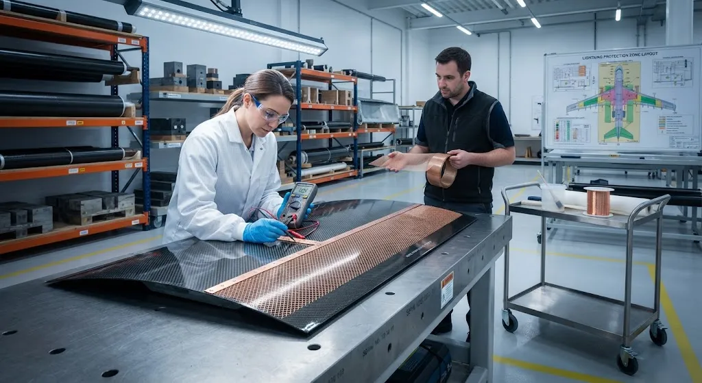
Aluminum airframes are naturally electrically continuous: the fuselage skin conducts lightning currents away from fuel and systems, and the metal shell acts as a shield that keeps electromagnetic interference out of avionics bays. Carbon fiber composites broke that assumption. A CFRP skin has an electrical resistivity roughly two orders of magnitude higher than aluminum along the fiber direction, and several orders of magnitude higher across the thickness, so current cannot spread through the structure the way it does through metal. The material must be engineered to carry lightning current and to block electromagnetic interference, which is why nearly every composite aircraft today integrates a metallic mesh or expanded foil into the outer piles of the laminate.
This article explains what the conductivity problem looks like in numbers, describes how lightning strike protection is zoned and applied, reviews expanded foil and mesh systems for EMI shielding, and closes with practical integration and inspection guidance for design and production teams.
Why Carbon Fiber Conducts Poorly
Commercial carbon fiber has an electrical resistivity of roughly 1.0-1.6 × 10⁻³ ohm-cm along the fiber axis, compared with 2.7 × 10⁻⁶ ohm-cm for aluminum. In the transverse and through-thickness directions the picture is far worse: laminate resistivity across the thickness typically lands between 0.1 and 1.0 ohm-cm because electrons must hop between insulating polymer layers and between poorly contacting fibers. The result is that a bare carbon laminate can carry only a small fraction of a lightning current pulse before the matrix overheats, vaporizes and delaminates, and it attenuates electromagnetic fields far less effectively than a conductive shell.
Conductivity also depends on fiber modulus. Pitch-based high-modulus fibers such as those in the M-series family reach resistivities near 7 × 10⁻⁴ ohm-cm, while standard and intermediate modulus PAN-based fibers sit in the low 10⁻³ range. These differences matter for thin edge caps and antenna ground planes, but no practical carbon product comes close to matching aluminum, which is why the industry standard answer is a metallic conductor integrated into the laminate rather than a fiber that conducts better.
Lightning Strike Protection: Zones and Mechanisms
Aircraft lightning protection design follows the zoned approach of SAE ARP 5412 and ARP 5414. Each zone on the airframe is classified by the severity of the attachment and swept-stroke threat, and the protection scheme is sized accordingly. The table below summarizes the typical threat levels and the protection treatments used in composite structures:
| Zone | Typical threat | Composite treatment |
|---|---|---|
| 1A (nose, wing tips, fin tip) | First return stroke up to 200 kA | Expanded copper foil 0.010-0.014 in, bonded under outer ply |
| 1B (leading edges, engine nacelles) | First return stroke, swept channel | Copper foil or 200-300 g/m² aluminum bronze mesh |
| 2A/2B (outer wing, fuselage crown) | Subsequent strokes and swept channels | Lighter expanded foil or fine bronze mesh |
| 3 (interior bays, non-attachment areas) | Induced currents, no direct attachment | EMI mesh where shielding is required |
The mechanism matters as much as the material. When a lightning channel attaches to a metal-mesh-protected surface, the mesh carries the current and spreads it over a large area, so the energy density stays below the threshold that would vaporize the epoxy matrix. The mesh is placed just beneath the outer surface ply, typically separated from structural carbon plies by a glass fiber isolation layer to prevent galvanic corrosion between copper and carbon. Part of the current still enters the carbon structure, so fasteners, joints and door surrounds are additionally bonded with conductive straps to keep every metallic element at the same potential.
Treated panels are then verified by high-current lab tests that reproduce zone 1A attachments, and by in-service lightning damage inspection programs. Rejectable damage on mesh-protected surfaces is usually localized to the outer ply, which is repairable in place, in contrast to an unprotected panel where the same strike can vaporize matrix deep inside the laminate.
EMI Shielding: Mesh and Foil Systems
EMI shielding is the same physical problem viewed at lower energy but higher frequency. Avionics bays, radar compartments, satellite payload modules and UAV electronics enclosures must attenuate fields generated by transmitters, power lines and external emitters so that sensitive receivers and flight computers operate predictably. Shielding effectiveness is conventionally reported in decibels: a panel that attenuates a field by 60 dB transmits only one millionth of the incident power. Bare CFRP typically provides 20-40 dB at best across the 100 MHz to 1 GHz range, whereas a well-integrated metallic mesh or foil system reaches 60-80 dB, closing the gap to aluminum's 70-90 dB.
- Expanded copper foil: Solid foil stretched into a diamond mesh, 0.010-0.014 in thick, offering the lowest resistance and highest shielding effectiveness; the standard choice for zone 1 protected regions and high-value payload cavities.
- Aluminum bronze woven mesh: 150-300 g/m² woven wire, drapeable and easy to lay into curved skins; the workhorse of EMI enclosures and secondary lightning zones, sometimes with a glass carrier for handling.
- Nickel- or copper-coated woven fabric: Flexible textile-grade mesh for seams, gaps and access panels, applied over apertures to maintain enclosure continuity.
- Conductive adhesives and straps: Mesh-to-structure bonding adhesives and metallic straps that carry current across joints, doors and bonded assemblies.
Integration quality dominates performance. Shielding effectiveness collapses if the mesh is torn, if adjacent panels are not electrically bridged, or if a grounding strap is omitted at a door or access cover. Design reviews therefore treat the mesh as an electrical circuit, not just a ply: cut-layout plans control the orientation of the diamond pattern, overlap zones are sized at 25-50 mm at splices, and every perimeter is terminated to a structural ground point.
Integration and Inspection Considerations
Metallic mesh is integrated during layup in three common forms. Co-cured mesh is laid directly under the outer ply and cured with the skin, which gives the best electrical bond and lowest weight. Co-bonded mesh is cured onto a skin and then bonded with adhesive for retrofit or repair applications. Bonded foil is adhered over a cured surface, typically for EMI retrofit of existing metallic parts or for local shielding around antenna apertures. Each route trades process simplicity against electrical continuity, and all three require careful handling to avoid wrinkles that create high-resistance paths.
Production teams should verify four things on every shielded panel: the mesh areal weight and alloy against the drawing, the overlap length at splices, freedom from tears and creases after debulk, and the presence of the glass isolation ply where galvanic isolation is specified. Surface finish is a common downstream surprise — a mesh pattern can print through thin outer plies and ruin cosmetic surfaces, so paint systems and surface films above mesh-protected areas must be qualified together with the electrical design.
Frequently Asked Questions
Why does carbon fiber need lightning protection when aluminum does not?
Aluminum conducts current along every axis, so a lightning strike spreads across the whole skin and the energy is dissipated over a large volume before the material can overheat. Carbon fiber conducts well only along the fiber axis and poorly across the thickness, so a bare CFRP panel cannot spread the strike current; the epoxy matrix overheats, vaporizes and delaminates at the attachment point. A metallic mesh or expanded foil embedded just under the outer ply carries and spreads the current instead, protecting the polymer matrix while keeping the metal structural weight to roughly 0.3-0.6 percent of the laminate mass.
Can EMI shielding be added to an already cured CFRP part?
Yes, for retrofit and repair. The most practical route is bonding expanded copper foil or a bronze mesh over the cured surface with a conductive adhesive, then terminating the new layer at structural ground points and bridging joints with metallic straps. For enclosure panels, an alternative is a conductive surface film or a spray-applied metal coating. The trade-off is a small weight and thickness penalty and the risk of galvanic corrosion where the added metal contacts carbon, which is managed with isolation layers and corrosion-inhibiting sealants at the interface.
Does the metal mesh weaken the composite structure?
The effect is small and is accounted for at design time. The mesh replaces or sits within the outer ply region, where it typically reduces laminate strength in that surface ply by a few percent; the copper is chemically isolated from the carbon fibers by a glass ply, which prevents galvanic corrosion. In structural sizing, the outer plies that carry the mesh are often treated as non-load-carrying for compression allowables, and the mesh's own stiffness contribution is ignored. The net weight and performance penalty of a 200-300 g/m² mesh system is usually below one percent of panel mass, which is why mesh protection is standard on composite airframes rather than an exception.
Conclusion
Bare carbon fiber cannot do what aluminum did for the airframe: carry lightning current across the structure and shield electronics from interference. The engineering answer is a deliberately placed metallic conductor — expanded copper foil in the highest threat zones, aluminum bronze mesh in secondary zones and EMI enclosures — bonded into the outer laminate with isolation, overlap and grounding rules that make the mesh behave like an electrical circuit rather than a decorative ply. Measured properly, these systems return shielding effectiveness in the 60-80 dB range and confine lightning damage to repairable surface plies.
For programs specifying electrically functional composites, the practical checklist is zone classification, mesh or foil selection, splice overlap and grounding discipline. Review our carbon fabric and prepreg range for laminates that pair well with foil and mesh protection layers, or contact our engineering team for shielding and lightning-protection integration support.
Part of topic
Related Articles
- Bio-Based Carbon Fiber Precursors: Lignin and Polyethylene for Low-Cost Production
- Large-Tow Carbon Fiber Cost Analysis: 48K vs 60K Price-Performance Comparison
- Carbon Fiber-Resin Interface Bonding: Surface Treatment and Coupling Agent Optimization
- Digital Twin for Carbon Fiber Manufacturing: Real-Time Process Monitoring and Defect Prevention
- Thermoplastic Carbon Fiber Welding for Automotive: Ultrasonic and Induction Welding Process Windows
- Large-Tow Carbon Fiber Wet Spinning: Process Optimization for 48K/60K Production Efficiency
Interested in Custom Carbon Fiber Products?
Contact our team for competitive pricing and technical specifications.
Get a QuoteRelated Products
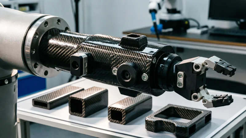
Carbon Fiber Robot End Effector Link — Custom Shape & Sensor Integration
Custom-shaped carbon fiber end effector links for robotic arms. Designed for automation integrators and research labs requiring lightweight, rigid connections between the robot wrist and gripper/tool. Can incorporate sensor mounting bosses, cable routing channels, and quick-change interfaces.

Custom Carbon Fiber Medical Device Components
Medical-grade carbon fiber components manufactured for imaging equipment, surgical instruments, and patient support systems. Carbon fiber's radiolucency (X-ray transparency) and high strength-to-weight ratio make it ideal for CT scanner beds, wheelchair frames, surgical robot arms, and MRI-compatible accessories. Biocompatible resin systems available.

Custom Carbon Fiber Musical Instrument Parts
Carbon fiber components for musical instrument manufacturing offering superior dimensional stability, low weight, and consistent acoustic properties. We produce carbon fiber bows, guitar necks, violin chin rests, drum shells, and wind instrument bodies. Carbon fiber instruments are immune to humidity changes and temperature fluctuations that affect wooden instruments.
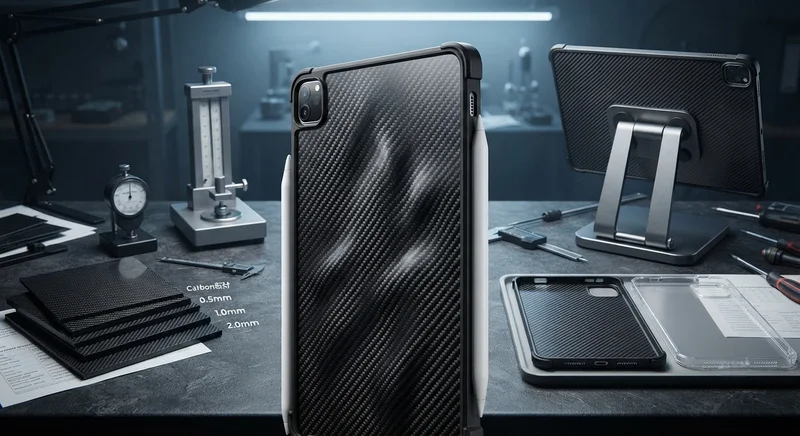
Carbon Fiber Tablet Case — Ultra-Light Protective Shell
Lightweight carbon fiber protective case for tablets and iPads. Molded from T700 3K prepreg with reinforced corner protection. Adds minimal weight while providing superior rigidity and drop protection compared to polycarbonate or silicone cases. Ideal for field workers, enterprise deployments, and professionals requiring durable tablet protection.
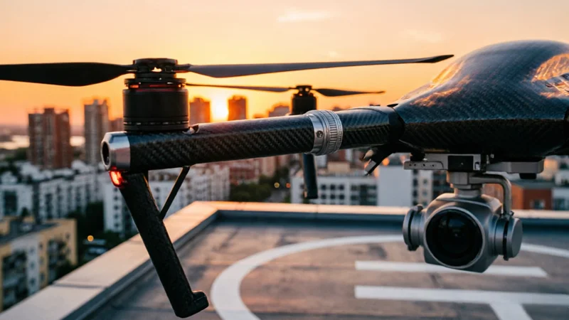
Custom Carbon Fiber Drone Arm — Lightweight & Vibration-Damping
High-modulus carbon fiber drone arms designed for industrial, agricultural, and surveying UAVs. Replace heavy aluminum arms with our custom-molded CFRP arms — 40-60% lighter with superior vibration damping for stable flight and sharper imaging.