
In autoclave composite manufacturing, the tool is the part. The mold surface defines the geometry of every carbon fiber laminate cured against it, and the way that mold expands and contracts through the cure cycle is written into the final dimensions of every part that touches it. A too
Introduction
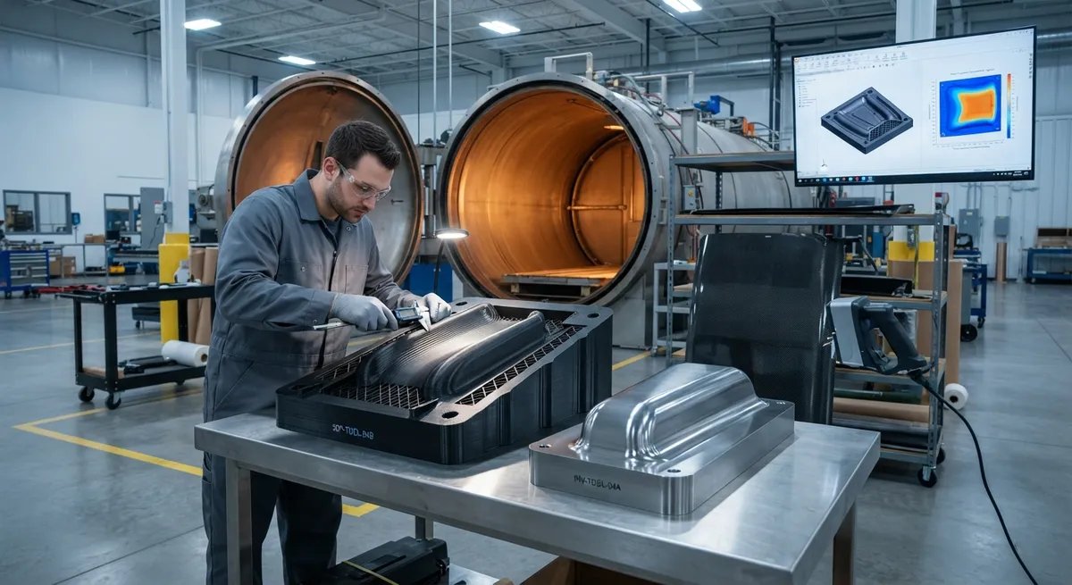
In autoclave composite manufacturing, the tool is the part. The mold surface defines the geometry of every carbon fiber laminate cured against it, and the way that mold expands and contracts through the cure cycle is written into the final dimensions of every part that touches it. A tool that is thermally mismatched to the part will produce parts that are consistently out of tolerance — not occasionally, but every time, at a predictable magnitude that grows with part size and cure temperature.
Two questions dominate composite tooling design today. First, how do you control the coefficient of thermal expansion (CTE) of the tool so that the cured part lands inside its dimensional specification? Second, given that traditional low-CTE tools such as Invar are expensive and slow to machine, when does 3D-printed tooling — which delivers complex mold geometry in days instead of months — become the right economic choice? This article answers both, with a focus on the data that a process engineer needs to make the trade-off.
Why CTE Matching Controls Dimensional Accuracy
During an autoclave cure, the tool and the laminate heat up together, expand together, and cool back down together. If the tool's CTE is different from the part's, the part cures at elevated temperature on an expanded tool surface and then, on cooling, tries to shrink onto a tool that is shrinking at a different rate. The result is a residual mismatch that appears as dimensional error in the cooled part — spring-in, warpage, and out-of-plane distortion in thin sections, and systematic size error in thick sections.
For a carbon fiber laminate, the in-plane CTE is near zero (typically 0 to 1.5 ppm/°C for high-modulus fibers) and slightly negative in some fiber directions, while the through-thickness CTE is much higher, in the range of 25-35 ppm/°C. This anisotropy is why the tool's CTE must be matched to the laminate in-plane behavior: a steel or aluminum tool, with a CTE of 12-23 ppm/°C, forces the part to conform to a surface that expands and contracts far more than the fibers themselves. The table below compares the tool materials most commonly evaluated for autoclave tooling:
| Tool material | CTE (ppm/°C) | Max service temp (°C) | Relative cost | Lead time |
|---|---|---|---|---|
| Invar 36 (Fe-36Ni alloy) | 1.2-2.0 | 200-230 | High (material + machining) | 6-16 weeks |
| Steel (mild / P20) | 11-13 | 250+ | Moderate | 4-10 weeks |
| Aluminum 6061 | 23-24 | 180-200 | Low-moderate | 3-8 weeks |
| Carbon fiber tooling | -1 to 2 (tailorable) | 180-200 | Moderate-high | 4-12 weeks |
| 3D-printed polymer (PPSU/PEI-based) | 30-55 (via compensation) | 150-200 | Low (design-dependent) | 1-3 weeks |
| 3D-printed carbon-filled composite | 10-25 (tailored via fiber) | 180-220 | Low-moderate | 1-3 weeks |
Because even a 1 ppm/°C mismatch accumulates into measurable error over a 2-4 meter part cured at 180°C, the industry rule of thumb is that tool CTE should match the laminate in-plane CTE within roughly 1-2 ppm/°C for tight-tolerance aerospace parts.
Invar: The Reference Standard and Its Real Cost
Invar 36 has been the reference tool material for aerospace composites for decades because its CTE of about 1.2-2.0 ppm/°C is close to the near-zero in-plane CTE of a carbon fiber laminate. A large Invar mold holds dimension through hundreds of cure cycles, which is why it remains the default for flight-critical skins, control surfaces, and fuselage panels.
The cost problem is twofold. Invar billet is expensive — several times the price of steel per kilogram — and machining a large contoured tool from solid Invar is slow and wastes most of the material. For a 3-meter fuselage panel mold, tooling cost commonly reaches hundreds of thousands of dollars and the schedule runs 8-16 weeks. This makes Invar impractical for prototype work, short production runs, and design iteration, where the tool is likely to be revised before it has amortized its cost.
3D-Printed Tooling: Geometry Freedom and Short Lead Times
Additive manufacturing removes the two constraints that make Invar expensive: the need for large solid billets and the machining time to remove metal from them. High-temperature polymer printing, typically fused filament fabrication (FFF) or large-format additive (LFAM) with materials such as PPSU, PEI (Ultem), and carbon-fiber-filled variants, produces near-net-shape molds directly from CAD. The practical consequences for composite shops are significant:
- Complex geometry at no extra cost: Curved, undercut, and conformal surfaces that require five-axis machining in metal are printed with the same effort as a flat panel, enabling integral cooling/heating channels and lightweight lattice back-structures.
- Lead time compression: A mold that takes 8-16 weeks to machine in Invar can be printed and finished in 1-3 weeks, which changes the economics of low-volume and prototype composite production entirely.
- CTE management by design: The effective CTE of a printed tool can be tuned by fiber loading, infill direction, and back-structure design, and the residual mismatch is compensated in the CAD model itself — the printed surface is offset to expand into the correct final geometry.
- Lower rework risk: A printed tool is cheap enough to discard and reprint after a design change, so iteration stops being a major cost event.
The limits are equally real: printed polymer tools have lower surface durability, need careful vacuum bag compatibility, and their high CTE (30-55 ppm/°C for unfilled polymer) must be compensated in design rather than ignored. For parts cured above roughly 200°C, printed tooling options narrow considerably.
Design Rules for Choosing a Tooling Strategy
There is no universal best tool material — the right choice depends on part size, tolerance, cure temperature, and program volume. The following decision sequence is a practical starting point for process engineers:
- Start with the tolerance budget: Define the maximum acceptable dimensional error, then calculate the CTE mismatch contribution over the cure temperature range. If the part is small (under 500 mm) and tolerance is moderate, even an aluminum tool may hold specification.
- Match CTE to the in-plane laminate behavior: For tight-tolerance aerospace parts, choose a low-CTE tool (Invar or carbon fiber tooling). For prototype and low-volume parts where absolute accuracy is secondary, compensated printed tooling is usually the faster path.
- Account for the part's own distortion: Spring-in and warpage from through-thickness CTE and resin shrinkage are corrected with compensation factors in the tool surface. This compensation applies regardless of tool material, so a printed tool designed with the same compensation is not inherently less accurate.
- Consider the full program economics: Amortize tool cost over expected part count. A $200,000 Invar mold is rational at 500 parts; a $30,000 printed mold that fails after 30-80 cycles can be reprinted several times before matching that cost.
Frequently Asked Questions
How many cure cycles can a 3D-printed composite mold survive?
Cycle life depends on the polymer, service temperature, and handling. High-temperature materials such as PPSU and carbon-filled PEI typically survive 20-80 autoclave cycles at 150-180°C before surface degradation requires refinishing, with some documented cases exceeding 100 cycles under controlled conditions. By contrast, Invar tools last thousands of cycles. The practical guidance is to reserve printed tooling for prototype, low-volume, and pilot production (tens of parts), and to validate cycle life with a test coupon printed from the same batch and material before committing a critical part to the tool.
Can 3D-printed tooling achieve the same dimensional accuracy as Invar?
Yes, within the operating envelope — but accuracy is achieved by compensation, not by matching CTE. Because the polymer CTE is higher than the laminate's, the printed tool surface is designed with an offset that makes the part shrink into tolerance as it cools. The achievable accuracy depends on the fidelity of the thermal model, the repeatability of the printing process, and the stability of the tool across cycles. For moderate-tolerance parts (roughly ±0.1-0.5 mm over a meter), printed tooling routinely meets specification; for the tightest flight-critical tolerances, low-CTE metallic or carbon tooling remains the safer choice. A growing practice is hybrid: printed tooling for prototypes to lock the design, Invar or carbon tooling for the production configuration.
What is the practical difference between Invar and carbon fiber tooling for CTE matching?
Invar offers a stable, near-zero CTE (1.2-2.0 ppm/°C) with excellent durability across hundreds of cycles, but it is heavy, expensive, and slow to produce. Carbon fiber tooling is built as a composite laminate, so its CTE can be tailored with layup orientation to be slightly negative, near zero, or slightly positive — and it is far lighter than Invar, which reduces autoclave handling loads. The trade-offs are higher up-front engineering (the tool itself must be master-molded or manufactured on a mandrel) and sensitivity to processing defects. For large parts where Invar weight becomes a handling problem, carbon tooling is often the preferred low-CTE option.
Conclusion
CTE matching is the single largest factor in composite tooling dimensional accuracy: it converts a thermal mismatch into a predictable, correctable error in the finished part. Invar remains the benchmark for tight-tolerance, high-cycle aerospace tooling, while 3D-printed molds have moved from novelty to a legitimate production tool for prototypes, low-volume runs, and complex-geometry parts where lead time and cost dominate. The winning strategy in most programs is a portfolio — printed tooling to iterate fast, low-CTE tooling to hold tolerance in production.
For engineers selecting tooling for a new composite program, the practical sequence is to fix the tolerance budget first, then choose the material that meets it at the lowest program cost. Explore our carbon fiber materials and tooling-grade reinforcements, or contact our engineering team to discuss tooling strategy, CTE compensation, and material selection for your autoclave process.
Part of topic
Related Articles
- Carbon Fiber Drone Blades and Propellers: Stiffness, Balance and Noise Reduction
- Fiberglass Filament Wound Tubes: Cost-Effective Alternative to Carbon Fiber
- Filament Wound Epoxy Tube Design: Wall Thickness, Fiber Angle and Load Optimization
- Filament Wound Epoxy Tubes: Testing Standards and Quality Assurance
- Filament Wound Epoxy Tubes Manufacturing: Process and Quality Control
- Filament Wound Fiberglass Tube: Process Parameters and Performance vs Carbon Fiber
Interested in Custom Carbon Fiber Products?
Contact our team for competitive pricing and technical specifications.
Get a QuoteRelated Products

Custom Carbon Fiber Medical Device Components
Medical-grade carbon fiber components manufactured for imaging equipment, surgical instruments, and patient support systems. Carbon fiber's radiolucency (X-ray transparency) and high strength-to-weight ratio make it ideal for CT scanner beds, wheelchair frames, surgical robot arms, and MRI-compatible accessories. Biocompatible resin systems available.
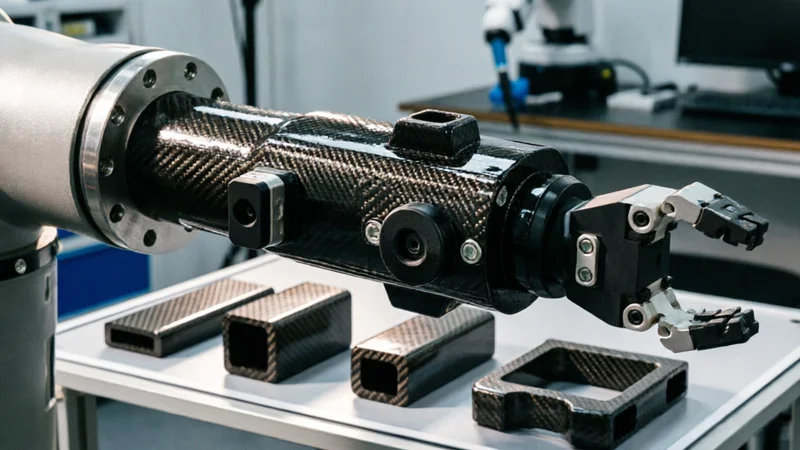
Carbon Fiber Robot End Effector Link — Custom Shape & Sensor Integration
Custom-shaped carbon fiber end effector links for robotic arms. Designed for automation integrators and research labs requiring lightweight, rigid connections between the robot wrist and gripper/tool. Can incorporate sensor mounting bosses, cable routing channels, and quick-change interfaces.
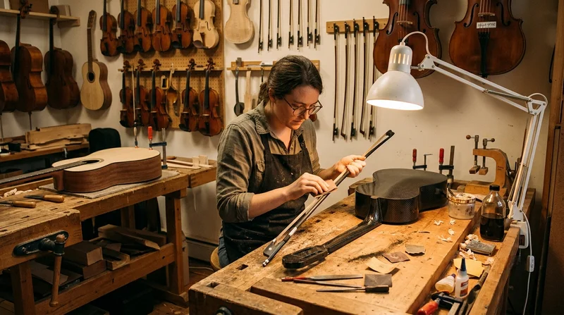
Custom Carbon Fiber Musical Instrument Parts
Carbon fiber components for musical instrument manufacturing offering superior dimensional stability, low weight, and consistent acoustic properties. We produce carbon fiber bows, guitar necks, violin chin rests, drum shells, and wind instrument bodies. Carbon fiber instruments are immune to humidity changes and temperature fluctuations that affect wooden instruments.
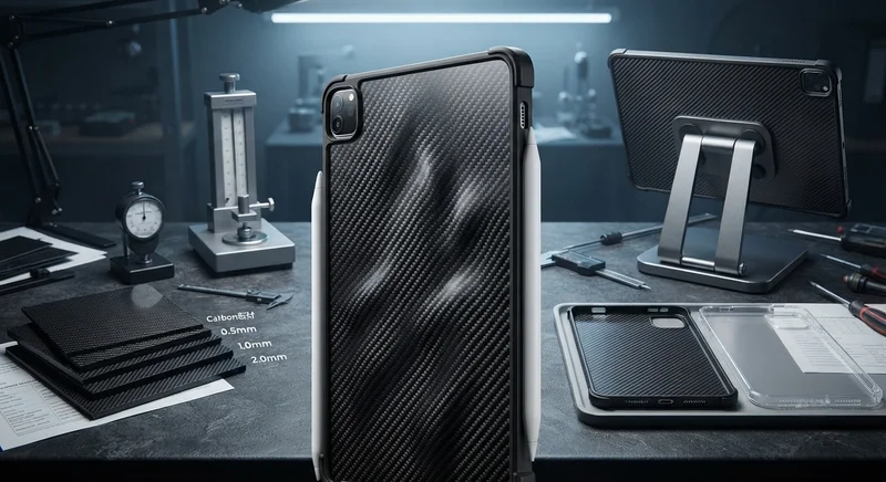
Carbon Fiber Tablet Case — Ultra-Light Protective Shell
Lightweight carbon fiber protective case for tablets and iPads. Molded from T700 3K prepreg with reinforced corner protection. Adds minimal weight while providing superior rigidity and drop protection compared to polycarbonate or silicone cases. Ideal for field workers, enterprise deployments, and professionals requiring durable tablet protection.
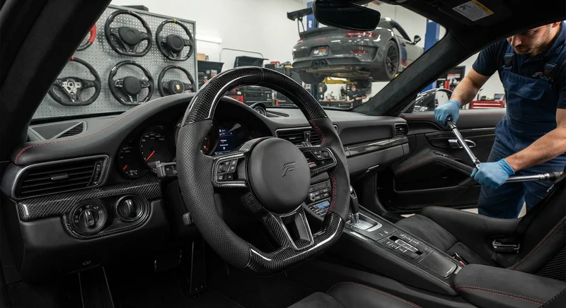
Carbon Fiber Steering Wheel — Custom Leather-Wrapped with CF Inlay
Custom carbon fiber steering wheel with genuine leather wrapping and carbon fiber inlay sections. Molded from T700 3K prepreg for maximum rigidity with a 30% weight reduction over OEM wheels. Available in D-shape (flat bottom) and round profiles. Direct bolt-on fitment for popular sports car and performance vehicle models. Custom stitching color and leather grade available.