
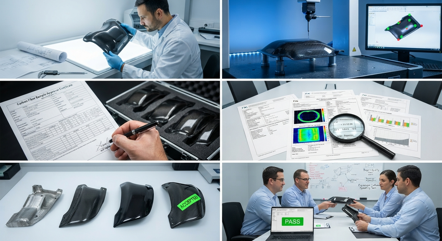
Comprehensive B2B guide to carbon fiber sample approval and prototyping. Covers technical drawing review, mold preparation, layup trials, NDT verification, FAI reporting, and the full approval workflow with 6-stage validation gates. Essential reading for procurement engineers and quality managers sourcing custom CFRP components.
Introduction to B2B Carbon Fiber Sample Approval
For B2B buyers sourcing custom carbon fiber reinforced polymer (CFRP) components — whether aerospace brackets, automotive structural inserts, medical device housings, or industrial machinery parts — the sample approval and prototyping phase is the most critical quality gate in the procurement cycle. Unlike off-the-shelf metallic parts with standardised dimensions and established supply chains, each custom CFRP component represents a unique combination of fiber architecture, resin system, cure cycle, and post-processing operations. A well-executed sample approval process ensures that the production-intent manufacturing process delivers components meeting dimensional tolerances, mechanical properties, surface finish requirements, and visual acceptance criteria before volume production commences.
The global carbon fiber composites market, valued at approximately $6.1 billion in 2025, is characterised by an increasing share of custom-engineered components — estimated at 38% of total market value, up from 28% in 2020. This trend toward customisation places greater emphasis on the sample-to-production transition. Industry data indicates that 73% of CFRP component quality issues identified during production can be traced back to inadequate sample approval protocols. This article presents a systematic B2B sample approval and prototyping workflow comprising six sequential validation gates, with a focus on the technical requirements, documentation, and acceptance criteria at each stage.
Stage 1: Technical Drawing Review and Design for Manufacturability (DFM)
The sample approval process begins with a structured review of the customer's technical drawings and 3D CAD models by the manufacturer's engineering team. The objective is to identify features that are difficult or impossible to produce using the selected manufacturing process and to propose DFM modifications before mold fabrication begins. Key review items include:
- Draft angles and undercuts: CFRP components require minimum draft angles of 1–3° per side for matched-die compression molding and 0.5–1° for autoclave-cured prepreg layups on rigid tools. Components with zero-draft vertical walls or internal undercuts require collapsible mandrels, soluble cores, or multi-piece tooling, which increase tool cost by 40–120% and extend lead time by 2–4 weeks.
- Radius specifications: Sharp internal corners (radius < 3 mm) cause fiber bridging, resin-rich zones, and stress concentrations. Minimum recommended inside radius is 3 mm (preferred 5 mm) for woven fabric laminates and 5 mm (preferred 8 mm) for unidirectional tape laminates. External corners should have a minimum radius of 1.5 mm to prevent edge chipping during trimming.
- Wall thickness transitions: Abrupt thickness changes create resin-rich pools, voids, and thermal gradients during curing. Recommended maximum thickness ratio between adjacent sections is 2:1, with taper transitions extending over a minimum of 10× the thickness difference. For components combining thin (1–2 mm) and thick (8–15 mm) sections, staged curing or co-cured sub-structures should be considered.
- Hole and cutout placement: Holes with diameter-to-thickness ratio < 3:1 are difficult to mold and are better produced by post-cure drilling or waterjet cutting. Minimum edge distance from hole center to part edge should be ≥ 2× hole diameter. Holes positioned in high-load regions should incorporate local reinforcement plies (scarfed patches or bonded doublers).
- Surface finish requirements: Cosmetic-grade surfaces (Class A for visible automotive exterior, Class B for visible interior) require specific tool surface preparation (1,000–3,000 grit polished steel or nickel-plated tools) and may require in-mold coating or post-cure painting. Functional surfaces (Class C) can be produced with standard tool finishes (400–600 grit).
| DFM Parameter | Target Value | Acceptable Range | Impact if Not Met |
|---|---|---|---|
| Minimum draft angle | 3° | 1–5° | Demolding damage, surface marring |
| Minimum inside radius | 5 mm | 3–8 mm | Fiber bridging, resin-rich zones, void content >3% |
| Maximum thickness ratio (adjacent sections) | 2:1 | 1.5:1 to 3:1 | Thermal gradient distortion, warp > 0.5 mm/100 mm |
| Minimum hole edge distance | 2× diameter | 1.5–3× | Delamination risk near hole edge |
| Surface finish (Ra) | 0.4 µm (Class A) | 0.2–1.6 µm | Visible fiber pattern, paint adhesion failure |
| Flatness tolerance | 0.1 mm/100 mm | 0.05–0.5 mm/100 mm | Assembly fit issues, gap > 0.2 mm |
Stage 2: Mold and Tooling Preparation
Once the technical drawings are reviewed and DFM modifications are agreed, the manufacturer proceeds with mold fabrication. The mold preparation timeline is typically the longest lead-time item in the prototyping phase, ranging from 2–8 weeks depending on tool complexity. Key considerations include:
- Tool material selection: Aluminum 6061-T6 is the standard tool material for prototype and low-volume production (up to 500 parts), offering good machinability, thermal conductivity (167 W/m·K), and moderate cost ($3,000–$12,000 for typical prototype molds). Steel (P20 or H13) is specified for high-volume production (> 2,000 parts) where durability and thermal uniformity justify the 2–3× higher tool cost. Nickel-shell tools (electroformed nickel) are used for complex geometries with tight tolerances (± 0.05 mm), offering excellent thermal uniformity (± 2°C across tool surface) and rapid heat-up times.
- Tool surface preparation: The tool surface finish directly determines the molded part's appearance. For Class A surfaces, the tool is polished to 1,000–3,000 grit, followed by application of three coats of high-temperature mold sealer (e.g., Henkel Frekote 700-NC or Chemlease 71-90) with intermediate 150°C flash cures. The mold release system is applied as five thin coats, each cured at 80°C for 15 minutes, with the final coat polished to remove excess release agent.
- Thermal survey and tool certification: Before first part production, the tool undergoes a thermal survey using 12–24 embedded thermocouples across the tool surface. Acceptance criteria: all thermocouple readings within ± 3°C of the specified cure temperature during the dwell phase, with heat-up rate uniformity within ± 20% of the average ramp rate. A thermal survey report is issued as part of the tool certification package.
Stage 3: Prototype Layup and Molding Trials
With the certified tool ready, the manufacturer conducts a series of prototype layup and molding trials. The number of trial iterations depends on part complexity and the manufacturer's experience with similar geometries:
- Trial 1 — Process development (typically 2–5 parts): Initial trials using the agreed-upon ply layup sequence, with manual placement of carbon fiber prepreg or dry fabric (for infusion). Key parameters recorded for each trial: ply orientation verification (± 2° accuracy per laser projection system), debulk vacuum dwell time (10–30 minutes between every 3–5 plies), and tack assessment at each ply interface. Parts are cured using the specified cure cycle and subjected to preliminary non-destructive inspection (ultrasonic C-scan or phased-array UT).
- Trial 2 — Dimensional verification (typically 3–8 parts): Full-dimensional inspection of molded parts using coordinate measuring machine (CMM) or structured-light 3D scanning. Key measurements include: overall length/width/height (± 0.3 mm typical), hole positions and diameters (± 0.1 mm), wall thickness (± 0.1 mm for 2–5 mm nominal thickness), flatness and profile tolerance (GD&T per ASME Y14.5). Non-conforming features are categorised as: (a) Critical — affects form, fit, or function (requires DFM revision or tool modification); (b) Major — outside tolerance but functionally acceptable (documented with deviation approval); (c) Minor — within 2× tolerance but visually noticeable (customer acceptance decision).
- Trial 3 — Mechanical property verification (destructive testing): Coupon-level mechanical testing per industry standards: ASTM D3039 tensile, ASTM D7264 flexural, ASTM D695 compression, and ASTM D2344 short-beam shear. Minimum five specimens per test direction per trial batch. Test results are compared to the design allowables specified in the customer's engineering specification. Acceptance criteria: mean value ≥ 100% of design allowable, individual values ≥ 85% of design allowable, coefficient of variation ≤ 8% within each test group.
Stage 4: Non-Destructive Testing and First Article Inspection
NDT is performed on 100% of prototype parts and on a statistically representative sample (AQL 1.0 per ISO 2859 or ANSI/ASQ Z1.4) of each pre-production batch. The NDT protocol for carbon fiber components typically includes:
- Ultrasonic testing (UT): Pulse-echo or through-transmission UT at 5–15 MHz frequency, with C-scan amplitude mapping for void content and delamination detection. Acceptance criteria: no delaminations exceeding 6 mm in any dimension, total void area ≤ 2% of inspected area, and individual void diameter ≤ 2% of the minimum local wall thickness.
- Shearography or thermography: Optical NDT methods for large-area inspection of sandwich panels and thin-gauge laminates (≤ 3 mm). Shearography reveals disbonds as out-of-plane deformation fringes under thermal or vacuum excitation. Accepted flaw size: ≤ 8 mm diameter for face sheet-to-core disbonds in sandwich structures.
- First Article Inspection (FAI) report: The FAI report is the formal quality deliverable documenting that the prototype manufacturing process produces parts conforming to all specified requirements. Per AS9102 (aerospace) or ISO 9001 (general industry), the FAI report includes: (a) Ballooned drawing with all characterised features numbered; (b) Dimensional measurement results for each feature (typically 50–200 measurements per part); (c) Material and process certifications (resin batch, fiber lot, prepreg out-time verification); (d) NDT results and mechanical test data; (e) Process parameter record (cure cycle chart, autoclave/vacuum pressure trace, temperature recorder strip).
| NDT Method | Defect Detection | Minimum Detectable Flaw | Application | Inspection Rate |
|---|---|---|---|---|
| Pulse-echo UT (5–15 MHz) | Delamination, voids, porosity | 3 mm diameter, 0.1 mm gap | Solid laminates > 1.5 mm thickness | 100% on prototypes; AQL 1.0 on production |
| Through-transmission UT | Delamination, voids, core disbond | 5 mm diameter | Sandwich panels, thick laminates | 100% on all aerospace-grade parts |
| Shearography | Face-sheet disbond, core crush | 8 mm diameter | Sandwich panels, thin laminates | 100% on prototypes; 25% on production |
| Infrared thermography | Near-surface disbond, moisture ingress | 5 mm depth, 10 mm lateral | In-service inspection, condition monitoring | As required per maintenance schedule |
| X-ray CT (200–450 kV) | Internal geometry, fiber orientation, porosity | 0.05 mm voxel resolution | Complex geometry, additively manufactured tooling | On first prototypes and for failure analysis |
Stage 5: Sample Submission and Customer Approval
After successful FAI completion, prototype samples (typically 3–10 parts) are submitted to the customer along with the complete FAI package. The customer's approval process typically involves:
- Dimensional review: The customer conducts independent dimensional inspection (CMM or manual gauging) on at least three sample parts. Dimensional acceptance per ASME Y14.5: 90% of characterised features within specified tolerance, 100% within 2× tolerance. All critical features (as defined in the ballooned drawing) must be within specification.
- Visual inspection: Incoming quality inspection per customer-defined visual acceptance criteria (typically ASTM D2565 or internally defined A/B/C surface rating). Common visual defects include: surface porosity (pin-holes < 0.5 mm diameter, maximum 5 per 100 cm²), fiber whitening in radii (fibre whitening width ≤ 2 mm for non-cosmetic surfaces), surface scratches (depth ≤ 0.05 mm for cosmetic surfaces), and surface contamination (discoloration, oil residue).
- Fitting trial and assembly verification: For components that are part of a larger assembly, a fitting trial is performed to verify dimensional compatibility at the assembly level. Acceptance: the sample part must fit within the specified assembly envelope without forced assembly (maximum acceptable interference: 0.2 mm), and all fastener holes must align within ± 0.3 mm of nominal position.
- Formal approval documentation: Upon successful completion of all review stages, the customer issues a formal sample approval certificate or sign-off on the FAI report. This document serves as the quality baseline for the pre-production and production phases. Typical turnaround time for customer review: 5–15 business days for standard components, 15–30 business days for complex aerospace safety-critical components.
Stage 6: Pre-Production Batch and Process Qualification
With sample approval secured, the manufacturer proceeds to a pre-production batch — a statistically significant run (typically 20–100 parts, representing 2–5% of the annual production volume) manufactured using the same tooling, process parameters, and inspection protocols as the approved samples. The pre-production batch serves to:
- Demonstrate process capability: Critical-to-quality (CTQ) dimensions and properties are measured from all pre-production parts. Process capability indices (Cpk and Ppk) are calculated per AIAG PPAP guidelines. Acceptance: Cpk ≥ 1.33 (4σ process) for all CTQ characteristics; Ppk ≥ 1.67 for safety-critical dimensions in aerospace applications. If Cpk < 1.33, the manufacturer must implement process improvements (e.g., tighter tool tolerances, automated ply placement, improved process control) and repeat the pre-production run.
- Validate production cycle time: The pre-production batch runs at the target production rate (e.g., 1 part per 45 minutes for compression molding; 1 part per 4 hours for autoclave-cured prepreg). Cycle time is recorded for each operation (layup, debulk, cure, demold, trim, inspection), and the total cycle is compared to the quoted production lead time. Acceptance: actual cycle time within ± 15% of quoted cycle time.
- Establish inspection baseline: Pre-production NDT results establish the in-process inspection baseline for production. Typical defect rates for well-qualified CFRP processes: void content 0.5–1.5% by volume, dimensional non-conformance rate 2–5% (mayor and minor), and reject rate < 3% for visual defects. Any significant deviation from these baselines triggers a process review.
Frequently Asked Questions
How long does a typical carbon fiber sample approval process take from technical drawing submission to approved sample?
The total timeline depends on part complexity, tooling requirements, and the manufacturer's current capacity. For a simple flat panel or moulding with existing off-the-shelf tool dimensions, the timeline can be as short as 3–5 weeks: 1 week for DFM review and drawing approval, 1–2 weeks for tool fabrication (using quick-turn aluminium tools), and 1–2 weeks for prototype trials and FAI. For complex geometries requiring new tooling fabrication (multi-piece steel molds with cooling channels, or nickel-shell tools), the timeline extends to 8–16 weeks: 2–3 weeks for DFM review, 3–6 weeks for tool fabrication and certification, 2–4 weeks for prototype trials across 3–5 iterations, and 2–3 weeks for FAI, customer review, and formal approval. B2B buyers should factor these timelines into their project planning and consider parallel-path tooling for critical-path components. Rush sample programs (2–3 weeks compressed timeline) are possible at a 50–100% cost premium, using expedited tool fabrication (CNC roughing with hand finishing) and accelerated cure cycles where the part design allows.
What are the most common reasons for sample rejection in carbon fiber B2B procurement?
Based on industry quality data from major CFRP component suppliers (2022–2025), the most common sample rejection reasons by frequency are: (1) Dimensional non-conformance — 34% of rejections, primarily hole position error (± 0.3 mm out of tolerance), wall thickness variation exceeding ± 0.15 mm, and flatness defects (warpage > 0.3 mm/100 mm). (2) Surface quality defects — 28% of rejections, including visible fiber pattern (print-through) on cosmetic surfaces, porosity/pin-holes exceeding acceptance limits, and surface contamination (mold release residue, dust particles embedded in the surface resin). (3) Mechanical property failure — 18% of rejections, most commonly compression strength below design allowable (particularly in thin-gauge laminates < 2 mm) and interlaminar shear strength (ILSS) below specification due to poor fiber-to-resin bonding. (4) Visual appearance issues — 12% of rejections, including color variation between batches (resin system batch-to-batch ∆E > 3.0 in CIELAB), fiber angle misalignment visible by eye (> 3° from specified orientation in woven fabrics), and trim line deviation. (5) Documentation deficiencies — 8% of rejections, where FAI or material certification documentation is incomplete, missing traceability data, or does not conform to the specified reporting format (AS9102, EN 9102, or equivalent). Understanding these rejection patterns allows B2B buyers to focus their incoming inspection resources on the highest-risk acceptance criteria.
Can sample approval be performed using 3D-printed tooling instead of conventional machined metal molds?
Yes, additively manufactured (3D-printed) tooling is increasingly used for prototype CFRP components, particularly for low-rate sample runs of 1–20 parts. The most common 3D-printed tool materials are: (a) Fused filament fabrication (FFF) with high-temperature thermoplastics — polyetherimide (PEI/ULTEM 9085) and polyetheretherketone (PEEK) printed tools, suitable for cure temperatures up to 150°C (ULTEM) and 250°C (PEEK). These tools cost 30–50% less than aluminium tools and can be produced in 2–5 days. However, they typically achieve a surface finish of Ra 3–8 µm (vs. Ra 0.4 µm for polished aluminium), limiting their use to Class B/C surfaces. (b) Stereolithography (SLA) with ceramic-filled epoxy resins — printed tools with a surface finish of Ra 1–3 µm after secondary polishing, suitable for Class A surface prototype parts. SLA ceramic-filled tools can withstand up to 120°C continuous and 150°C short-term. (c) Binder jetting with stainless steel or Inconel — full-density metal tools produced by binder jetting + sintering, achieving 95–99% density with surface finish Ra 5–10 µm (requiring secondary machining for Class A surfaces). Binder jet tools offer the highest thermal durability (up to 600°C) and are suitable for high-temperature polyimide resin systems. Key trade-offs for 3D-printed sample tooling: lead time reduction of 50–75% vs. machined metal, tool cost reduction of 30–60%, but tool life limited to 20–100 parts (vs. 1,000–10,000+ for machined steel). For sample approval, AM tooling is an excellent option; for pre-production and volume production, conventional machined metal tooling should be qualified in parallel using the same approved process parameters.
Part of topic
Related Articles
- Recycled Carbon Fiber Market Forecast 2030: Technology Maturity and Commercialization Path
- South Korea Carbon Fiber Market 2026: Hydrogen Economy and Shipbuilding Innovation
- Wind Turbine Blade Leading Edge Protection 2026: Polyurethane, Tape, and Metallic Shield Solutions
- China Carbon Fiber Overcapacity 2026: Price War Impact and Industry Consolidation
- India Carbon Fiber Market 2026: Wind Energy, Aerospace, and Defense Expansion
- PAN Precursor Market 2026: Acrylonitrile Supply and Carbon Fiber Cost Structure
Interested in Our Products?
Contact our team for competitive pricing and technical specifications.
Get a QuoteRelated Products

Custom Carbon Fiber Medical Device Components
Medical-grade carbon fiber components manufactured for imaging equipment, surgical instruments, and patient support systems. Carbon fiber's radiolucency (X-ray transparency) and high strength-to-weight ratio make it ideal for CT scanner beds, wheelchair frames, surgical robot arms, and MRI-compatible accessories. Biocompatible resin systems available.

Square Carbon Fiber Tube — 3K Twill T700
Square cross-section carbon fiber tube manufactured with 3K twill weave for torsional strength. Preferred for structural frames, trusses, and support columns where rectangular geometry offers design flexibility.

Carbon Fiber Plate — 3K Twill T700 3.0mm
Medium-thickness 3.0mm carbon fiber plate offering significantly higher load capacity while maintaining attractive 3K twill finish. Suitable for structural brackets, reinforcement plates, and load-bearing panels.

Carbon Fiber Plate — 3K Twill T700 1.5mm
Thin 1.5mm carbon fiber plate with 3K twill weave surface. Lightweight and stiff, commonly used for covers, panels, drone bodies, and applications requiring a premium aesthetic appearance.

Carbon Fiber Fishing Rod Blank
High-quality carbon fiber fishing rod blank manufactured from multiple grades of Toray carbon fiber cloth. Available in a wide range of lengths, powers, and actions for freshwater and saltwater applications. Suitable for OEM rod building.