
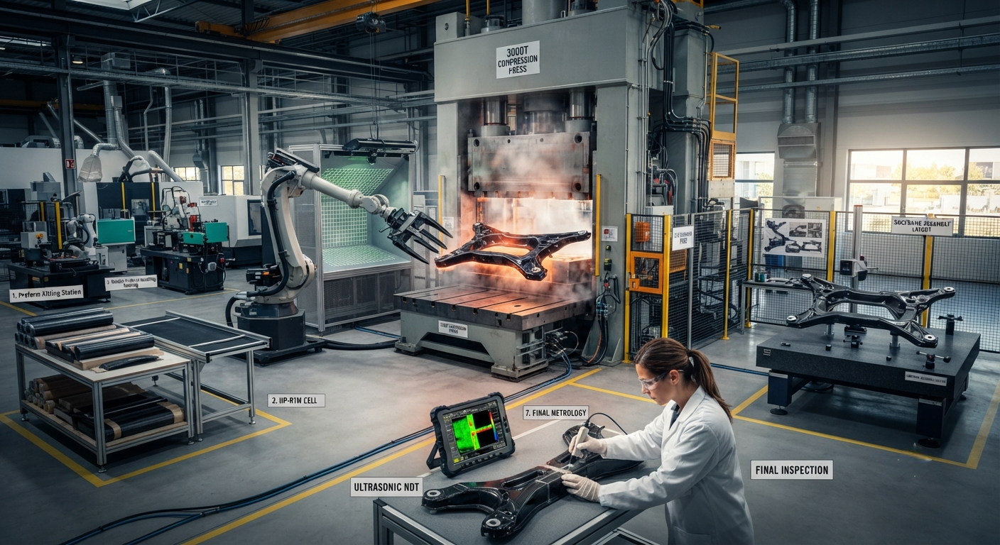
Technical B2B analysis of carbon fiber automotive subframes — replacing welded steel chassis structures with bonded composite assemblies. Covers design principles, HP-RTM and compression molding processes, structural adhesive bonding technology, metal insert integration, crash performance, and OEM adoption programs from BMW, Ford, and NIO with detailed cost analysis.
Carbon Fiber Automotive Subframes: The Next Frontier in Vehicle Lightweighting
Automotive subframes — the structural modules that carry the engine, suspension, steering rack, and front/rear axles — are among the heaviest single components in modern vehicle architectures. A typical front subframe in a D-segment sedan (BMW 5 Series, Mercedes-Benz E-Class, Audi A6) weighs 18–28 kg in high-strength steel and 12–18 kg in aluminum alloy. Replacing these welded steel or aluminum structures with carbon fiber composite assemblies offers weight reductions of 40–65% while simultaneously enabling functional integration — consolidating 40–60 individual stamped and welded steel components into a single molded composite structure with bonded metal inserts. This article provides a comprehensive technical analysis of carbon fiber composite subframes, covering design principles, bonding technologies, material selection, manufacturing processes, crash performance, and the current state of OEM adoption.
The business case for carbon fiber subframes has strengthened considerably since 2023, driven by three converging trends: (1) the accelerating transition to electric vehicles, where every kilogram of unsprung mass reduction translates directly to range improvement; (2) the maturation of high-volume composite manufacturing processes — particularly high-pressure resin transfer molding (HP-RTM) and compression molding of woven prepreg — capable of producing subframes at cycle times compatible with automotive production rates (3–8 minutes per part); and (3) the development of structural adhesive and mechanical interlock bonding technologies that achieve joint strengths exceeding the parent composite material's interlaminar shear strength.
Design Principles for Composite Subframes
The design of a carbon fiber composite subframe differs fundamentally from an equivalent steel or aluminum structure. While metallic subframes rely on closed-section tubes, stamped sheet metal panels, and welded joints to create a stiff, load-bearing assembly, composite design exploits the material's anisotropy — placing fiber where loads are highest and removing material where they are not. Key design principles include:
- Load-path-optimized fiber architecture: Finite element analysis (FEA) of the subframe under static and dynamic loads — including vertical suspension loads (3–5 g), lateral cornering forces (0.8–1.2 g), braking forces (1.0–1.5 g), and engine/transmission torque reaction (500–1,200 N·m) — defines the principal stress trajectories. Carbon fiber plies are then oriented to align with these load paths, with 0° (axial) plies carrying tensile and compressive forces along the subframe rails, ±45° plies managing torsional loads at suspension pickup points, and 90° plies providing hoop strength at bolted joint inserts.
- Variable thickness and ply tailoring: Composite subframes employ ply drop-off and local reinforcement to vary thickness from 2–3 mm in low-load regions (cross-members between main rails) to 8–15 mm at high-load regions (suspension mounting points, engine mount brackets, subframe-to-body attachment points). This variable-thickness capability — impossible with stamped steel or extruded aluminum — enables mass distribution that precisely matches the local stress field, eliminating the uniform-thickness penalty inherent in metallic designs.
- Rib, gusset, and sandwich construction: Carbon fiber's high specific stiffness enables the use of thin-wall (1.5–2.5 mm) skins stabilized by integral ribs and gussets. A typical composite front subframe incorporates 8–15 integrally molded ribs and 4–6 gusseted corner reinforcements that provide bending and torsional stiffness without the mass penalty of thickening the entire skin. In regions requiring extremely high bending stiffness with minimal mass — such as the engine mount cross-member — a foam or honeycomb core sandwich construction is employed, with carbon fiber face sheets stabilizing the core against shear buckling.
- Metal insert integration: Steel or titanium inserts are required at all bolted connection points — subframe-to-body mounts (4–6 points), suspension arm attachment points (8–12 points), steering rack mounts (2–4 points), and engine/transmission mounts (3–4 points). These inserts are either co-cured (placed in the mold before resin infusion, creating a chemical bond with the composite) or bonded post-cure using structural epoxy adhesives with shear strengths exceeding 30 MPa. Co-cured inserts offer 20–40% higher pull-out strength but require precise positioning within the mold, adding 10–20% to tooling complexity.
| Parameter | Steel Subframe (HSLA) | Aluminum Subframe (6061-T6/A356) | CF/Epoxy Subframe (HP-RTM) | CF/PA6 Subframe (Compression Molded) |
|---|---|---|---|---|
| Mass (kg) | 22–28 | 12–18 | 6–10 | 5.5–9.5 |
| Torsional stiffness (kN·m/rad) | 18–25 | 14–20 | 22–30 | 18–26 |
| Specific stiffness (kN·m/rad/kg) | 0.7–1.0 | 0.9–1.3 | 2.5–4.0 | 2.2–3.5 |
| Ultimate tensile load (kN) — main rail | 120–180 | 80–120 | 150–220 | 130–190 |
| Fatigue life (cycles at ±50% ultimate) | >10⁶ | >10⁶ | 3×10⁵–8×10⁵ | 5×10⁵–1×10⁶ |
| Corrosion resistance | Poor (requires coating) | Moderate (galvanic risk) | Excellent (inherent) | Excellent (inherent) |
| Dimensional tolerance (mm) | ±1.0–2.0 | ±0.8–1.5 | ±0.3–0.8 | ±0.5–1.0 |
| Parts consolidated (single subframe) | 40–60 | 25–40 | 2–6 (molded + bonded) | 2–6 (molded + bonded) |
| Cycle time (min) | N/A (assembly line) | N/A (assembly line) | 4–8 | 3–6 |
| Relative cost per subframe (10k/yr) | 1.0x (baseline: $80–150) | 1.5–2.0x | 3.5–5.5x | 3.0–4.5x |
| Relative cost per subframe (100k/yr) | 1.0x | 1.3–1.8x | 2.5–3.5x | 2.0–3.0x |
Bonded Composite Assembly Technology
The most significant technical challenge in carbon fiber subframe design is joining the individual molded components into a complete assembly that meets the structural integrity, fatigue life, and crashworthiness requirements of an automotive chassis structure. Unlike steel subframes, which are assembled by robotic welding (MIG, MAG, or spot welding) at rates of 50–100 welds per subframe, composite subframes must be joined using adhesive bonding, mechanical interlocking, or a combination of both — a technology set broadly referred to as bonded composite assembly.
Structural adhesive bonding is the primary joining method for composite subframe assembly. Two-part epoxy and polyurethane structural adhesives with shear strengths of 25–40 MPa and peel strengths of 3–6 N/mm are applied to the bond surfaces at a controlled bond line thickness of 0.2–1.0 mm. The bonding process requires precise surface preparation — typically atmospheric plasma treatment or grit blasting followed by solvent cleaning — to achieve the necessary surface energy for optimal adhesion (> 45 mN/m surface energy target). The adhesive is cured at 120–180°C for 15–45 minutes, either in a separate bonding fixture oven or in the same press tool used for the final forming operation (in-mold bonding). Key advantages of adhesive bonding include: uniform stress distribution across the joint (eliminating the stress concentrations inherent in spot welding or bolting), galvanic isolation between carbon fiber and any metallic inserts or attachments, and the ability to join dissimilar materials (carbon fiber to titanium, steel, or aluminum).
Mechanical interlocking — through overmolded ribs, tongue-and-groove features, or co-cured threaded inserts — provides secondary load paths and fail-safe redundancy to the bonded joints. In a well-designed bonded composite subframe, the adhesive carries 70–85% of the service load, with mechanical interlock features carrying the remaining 15–30% and ensuring that the joint retains structural integrity even in the event of partial adhesive failure (e.g., from manufacturing defects or impact damage). Automotive OEM specifications typically require that bonded composite joints retain at least 50% of their design load capacity after the adhesive bond is intentionally broken (the "fail-safe" condition), with the mechanical interlock alone providing this residual capacity.
Hybrid bonding — adhesive plus mechanical fasteners — is sometimes employed at the most critical joints, such as the subframe-to-body attachment points and the suspension lower control arm mounts. In these locations, structural bolts or rivets are installed through the adhesive bond line while the adhesive is still in its green (partially cured) state, creating a bond that combines the stress-distributing advantages of adhesive with the positive clamping force and peel resistance of mechanical fasteners. Hybrid joints in composite subframes have demonstrated fatigue lives 2–3× longer than adhesive-only joints when tested under combined peel and shear loading at -30°C to +85°C.
Material Selection and Manufacturing Processes
Three material-process combinations have emerged as leading candidates for production carbon fiber subframes, each with distinct advantages and application windows:
- CF/Epoxy via HP-RTM (High-Pressure Resin Transfer Molding): Dry carbon fiber preforms (braided, NCF, or woven) are placed in a heated steel mold and injected with epoxy resin at 80–160 bar injection pressure. Cure time: 3–6 minutes at 120–150°C. Fiber volume fraction: 50–58%. This process is preferred for structural subframe components where high fiber volume, low void content (< 1%), and aerospace-grade mechanical properties are required. HP-RTM tooling cost: $500,000–$1,500,000 per mold set. Recommended for annual volumes of 20,000–80,000 units.
- CF/PA6 via compression molding: Woven carbon fiber prepreg with polyamide 6 (PA6) matrix is cut, stacked, and formed in a compression press at 260–290°C and 80–150 bar. Consolidation time: 2–4 minutes. Fiber volume fraction: 45–52%. The thermoplastic matrix provides superior impact resistance (Charpy impact 2–3× higher than epoxy), recyclability, and weldability — PA6 subframe components can be joined by vibration welding or induction welding in addition to adhesive bonding. Tooling cost: $400,000–$1,200,000 per mold set. Recommended for annual volumes of 30,000–120,000 units.
- CF/Epoxy with discontinuous fiber (Sheet Molding Compound — SMC): Carbon fiber SMC with 25–50 mm chopped fiber at 40–50% volume fraction is compression molded at 135–160°C and 50–120 bar. This process offers the lowest material cost and fastest cycle times (2–4 minutes) but delivers the lowest mechanical properties — approximately 40–60% of the tensile strength and stiffness of continuous-fiber HP-RTM composites. SMC subframes are suitable for non-structural cross-members and brackets where the primary requirement is mass reduction rather than maximum structural performance.
OEM Programs and Production Applications
Several automotive OEMs have progressed carbon fiber subframes from research projects to production or near-production applications. BMW has been the most aggressive adopter, introducing carbon fiber front subframe components in the iX (2021) and i7 (2022) and expanding to full carbon fiber front subframes in the Neue Klasse platform (scheduled for 2025–2026 production launch). The Neue Klasse front subframe — manufactured by Magna International using HP-RTM with carbon fiber/epoxy — is reported to weigh 7.2 kg, a 62% reduction from the steel front subframe it replaces in the current CLAR platform, while matching or exceeding the steel structure's torsional stiffness (24 kN·m/rad). The subframe incorporates 38 individual steel and aluminum inserts co-cured during the HP-RTM process, consolidating what was previously 52 separate stamped and welded steel components into a single molded structure with two adhesive-bonded sub-assemblies.
Ford Motor Company has evaluated carbon fiber front subframes for the F-150 Lightning electric pickup truck through its collaboration with Dow Automotive and Teijin. A prototype carbon fiber/PA6 compression-molded subframe demonstrated a 55% mass reduction versus the production aluminum subframe (8.5 kg vs 18.9 kg) while meeting all structural durability, NVH, and crashworthiness targets. Ford's evaluation program reported bolt hole stress relaxation under thermal cycling (90–95% load retention after 1,000 cycles from -40°C to +90°C) as an acceptable outcome, with the polyamide matrix showing better creep resistance than initially projected.
Chinese OEM NIO has developed a carbon fiber front subframe for its ET9 flagship sedan, using a hybrid manufacturing approach combining HP-RTM primary structure with compression-molded PA6 brackets and attachment features. The NIO subframe — produced in collaboration with Chinese composite manufacturer Jiangsu Hengshen — weighs 8.2 kg and supports a 520 kW dual-motor powertrain while meeting C-NCAP 2024 five-star crashworthiness requirements. The production rate of 15,000 units per year (single shift) was achieved through a two-cavity HP-RTM tool with a 6-minute cycle time.
Frequently Asked Questions
What is the expected service life of a carbon fiber composite subframe, and how does it compare to steel?
The design service life of a carbon fiber composite subframe is typically specified at 300,000 km or 15 years — equivalent to the standard durability target for steel and aluminum chassis structures. However, the failure modes and degradation mechanisms differ significantly between composite and metallic subframes. Steel subframes fail primarily through corrosion (in regions with road salt exposure) and fatigue crack initiation at weld joints and stress concentrations. Aluminum subframes are susceptible to galvanic corrosion at bi-metallic interfaces and fatigue failure at cast-to-wrought transitions. Composite subframes — assuming proper material selection and manufacturing quality — are immune to electrochemical corrosion and exhibit no fatigue limit in the traditional sense (a characteristic shared with all polymer-matrix composites). The primary degradation mechanisms for composite subframes are: (1) moisture absorption by the polymer matrix (epoxy absorbs 1.5–3% moisture by weight at saturation, which reduces glass transition temperature by 10–20°C and decreases interlaminar shear strength by 10–15%); (2) thermal cycling fatigue (differential thermal expansion between carbon fiber (-0.5 × 10⁻⁶/°C) and the polymer matrix (50–80 × 10⁻⁶/°C) generates microcracks in the matrix after thousands of thermal cycles); (3) UV degradation of exposed surfaces (mitigated by paint or in-mold coating); and (4) impact damage from stone strikes and road debris (which may create subsurface delamination not visible during visual inspection). In practice, automakers validate composite subframes through accelerated durability testing equivalent to 400,000–600,000 km of service, applying a safety factor of 1.5–2.0× to the 300,000 km design target. Field data from BMW's Carbon Core vehicles — which have accumulated over 3 million fleet kilometers on carbon fiber chassis components since 2015 — indicates that composite subframe reliability is comparable to or better than equivalent steel structures, with zero reported field failures attributable to composite material degradation as of Q2 2026.
How does a carbon fiber subframe affect vehicle crashworthiness compared to a steel or aluminum subframe?
The crash behavior of a carbon fiber subframe differs fundamentally from metallic subframes, requiring specific design adaptations rather than direct material substitution. Steel subframes absorb impact energy through plastic deformation (bending, folding, tearing) over a long crush stroke (150–300 mm at the front subframe). Carbon fiber subframes absorb energy through progressive crushing (fiber fracture, matrix cracking, delamination, friction between fragments) — a mechanism that occurs at higher load intensity but over a shorter stroke. The key crashworthiness considerations for composite subframes include: (1) Crash load management: the composite subframe must be designed to fail at a controlled load level that does not exceed the body structure's load capacity. This is achieved through trigger features — local strength reductions (grooves, chamfers, reduced wall sections) that initiate progressive crushing at a predetermined load. The peak crush force must be limited to 80–120% of the mean crush force to avoid rapid deceleration spikes that could injure occupants. (2) Load path compatibility: in a front collision, the subframe must transfer load to the main longitudinal rails at a rate compatible with the crash box and rail crush characteristics. A composite subframe that is too stiff relative to the crash box will cause premature buckling of the body structure; one that is too compliant will not engage the crash energy management system effectively. (3) Subframe separation control: in severe crashes (> 30 km/h impact), the subframe must either remain attached to the body (to maintain steering and suspension geometry) or separate in a controlled manner (to prevent the engine/transmission from being pushed into the passenger compartment). Carbon fiber subframes are designed with defined fracture zones at the subframe-to-body mount points that separate at a calibrated load threshold. (4) Thermal event performance: in the event of a post-crash fire, epoxy matrix composites will burn and lose structural integrity. However, automotive OEM specifications require that the subframe maintain sufficient structural integrity to allow occupant extraction — typically 2–5 minutes of fire exposure per FMVSS 302 (flammability of interior materials) and the more severe FMVSS 301 (fuel system integrity) standards. Flame-retardant epoxy formulations and intumescent coatings are available for subframe applications where post-crash fire survivability is a specific requirement.
What is the total system cost impact of switching from a steel subframe to carbon fiber, including secondary weight savings?
The total system cost analysis for carbon fiber subframe adoption must account for primary and secondary cost effects across six categories. (1) Direct component cost: a carbon fiber subframe costs 2.5–5.5× the equivalent steel subframe (as shown in the table above), representing $200–600 in added direct cost per vehicle at low volume and $100–300 at high volume. (2) Secondary mass savings: every kilogram of mass removed from the subframe enables 0.5–0.8 kg of secondary mass reduction in suspension components, springs, dampers, and body structure attachments (the mass decompounding factor). For a 12–20 kg mass reduction at the subframe, this yields 6–16 kg of additional mass savings elsewhere, worth $3–8/kg in cost avoidance. (3) Parts consolidation savings: consolidating 40–60 stamped and welded steel parts into 2–6 molded composite components eliminates stamping dies ($50,000–$200,000 per die, 6–10 dies eliminated), welding fixtures ($30,000–$80,000 per fixture), and assembly labor (approximately 15–25 minutes per subframe at $45–65/hour). The parts consolidation savings typically total $80–$180 per subframe at production volumes above 50,000 units per year. (4) Logistics and handling: a 12–20 kg lighter subframe reduces shipping costs by $0.50–$1.50 per unit (ocean freight to assembly plant) and eliminates the need for corrosion-protection packaging (rust-preventative coatings, VCI bags, and desiccant packs) required for steel subframes — adding $3–$8 per unit savings. (5) Corrosion warranty reduction: steel subframe corrosion-related warranty claims cost automakers an average of $15–$40 per vehicle over a 10-year service life in road-salt regions (North America, Northern Europe, China). Carbon fiber's inherent corrosion immunity eliminates these costs entirely. (6) Battery range contribution (EV-specific): for electric vehicles, the 12–20 kg mass reduction at the front subframe extends driving range by approximately 1.5–3.0 km (WLTP cycle), which at $130/kWh battery pack cost and approximately 0.2 kWh/km energy consumption is worth $40–$80 in battery cost reduction per vehicle. The net system cost premium for a carbon fiber subframe, accounting for all six factors at 50,000 units/year production volume, is approximately $50–$180 per vehicle — a premium that is already cost-justified for EV platforms with aggressive range targets and premium vehicle segments where mass reduction enables performance differentiation. At production volumes above 100,000 units per year, the net system cost is projected to approach parity with aluminum subframes by 2028–2030 and with steel subframes by 2032–2035.
Part of topic
Related Articles
- Carbon Fiber Mooring for Floating Offshore Wind: Fatigue and Corrosion in Deep Water
- Carbon Fiber Bicycle Frame Optimization: Layup Design and Manufacturing for Competitive Racing
- Carbon Fiber CFRP Retrofit for Infrastructure: Bridge and Building Seismic Strengthening
- Carbon Fiber Medical Imaging Equipment: Lightweight Gantry and Couch Structures for MRI/CT
- Carbon Fiber EV Battery Enclosures: Crash Safety and Electromagnetic Shielding Design
- Carbon Fiber Structures for Low-Altitude Economy: UAV Airframes and eVTOL Components