
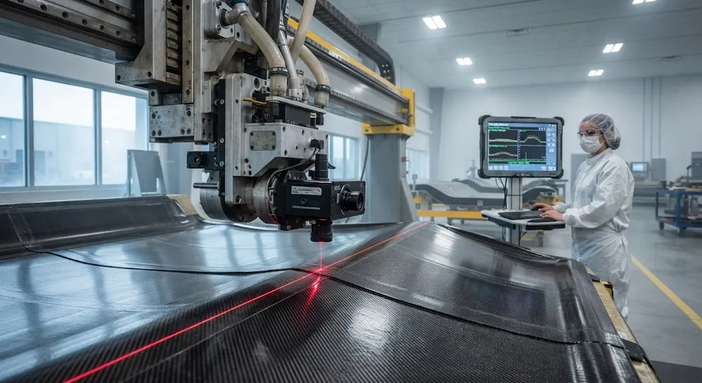
Automated fiber placement has become the backbone of large composite structure manufacturing, from business jet wings to rocket motor casings and wind turbine spar caps. A modern AFP gantry can lay carbon fiber tows at hundreds of meters per minute, placing narrow strips of prepreg with
Introduction
Automated fiber placement has become the backbone of large composite structure manufacturing, from business jet wings to rocket motor casings and wind turbine spar caps. A modern AFP gantry can lay carbon fiber tows at hundreds of meters per minute, placing narrow strips of prepreg with robotic precision over tool surfaces that would be impossible to handle by hand. Yet the placement head is only half of the productivity story. The other half is verification: confirming that every tow landed where it was supposed to, with gaps, overlaps, and edge tolerances inside specification. When that verification happens after layup, the resulting inspection-rework loop becomes the single largest consumer of machine time in many production cells.
Industry surveys of AFP production consistently attribute roughly 60% of machine downtime to inspection and rework cycles, rather than to the placement process itself. The response has been a shift in inspection architecture: instead of scanning cured parts offline, manufacturers are mounting laser line-scanners directly on the placement head and measuring the laminate surface as it is laid. This article examines why inspection-rework dominates AFP downtime, how inline laser line-scanning works, what data it produces, and the integration decisions that determine whether the technology pays for itself on a gantry or a robot.
Why Inspection-Rework Dominates AFP Downtime
AFP downtime breaks down into a familiar set of categories, but their relative weight surprises many new users of the technology. Machine maintenance, material handling, and programming all matter, yet the largest single block is the loop that runs after a course is laid: offline inspection, defect marking, and manual or automated rework. The table below summarizes the typical distribution observed in aerospace AFP cells:
| Downtime Category | Share of Total Downtime | Typical Root Cause | Reduction Path |
|---|---|---|---|
| Inspection and rework | 55-65% | Offline scanning, defect review, manual repair | Inline line-scan with closed-loop control |
| Material handling | 15-20% | Creel changes, tow splicing, prepreg life limits | Redundant creels, automated splicing |
| Machine and maintenance | 10-15% | Head cleaning, sensor recalibration | Predictive maintenance, self-cleaning optics |
| Programming and simulation | 5-10% | Path trial runs, off-line verification | Simulation-driven path release |
The inspection-rework loop is expensive for three compounding reasons. First, defects discovered after a course is complete often require stopping the machine, unpausing the process, and sometimes re-laying an entire section. Second, offline inspection methods such as structured-light scanning or thermal cameras require separate equipment, separate floor space, and dedicated operators. Third, when defects are only found post-cure, a single missed gap can force rework of a part that has already consumed hours of layup and oven time. Moving measurement into the placement cycle attacks all three cost drivers at once.
How Inline Laser Line-Scanners Work
A laser line-scanner projects a narrow line of light onto the laminate surface and uses a camera to record the deformation of that line across the field of view. From the distortion of the line, the sensor reconstructs a height profile of the surface in a single pass, at rates of hundreds to thousands of profiles per second. Mounted on the AFP head beside the compaction roller, the scanner continuously observes the tow band immediately after it is placed, before the next course covers it. The resulting data stream gives the control system a direct measurement of three quantities that drive laminate quality:
- Gap width: the distance between adjacent tows within a course, typically held below 1-3 mm for aerospace laminates, where oversized gaps become resin pockets or structural weak points.
- Overlap: the doubly covered region where a tow edge crosses its neighbor, creating local thickness build-up and fiber waviness that degrade compression strength.
- Tow drop and edge location: the precise position of each tow start and end, enabling verification that steering angles and ply boundaries match the programmed path.
The physics of the measurement matters as much as the optics. Laser line-scanning is a geometric measurement: it reads the surface profile independent of material temperature, emissivity, or cure state, which makes it complementary to thermal imaging rather than a replacement for it. Thermal cameras detect temperature anomalies that may indicate foreign object debris, moisture, or heater faults; the line-scanner measures geometry. A complete in-process vision system pairs the two, with the scanner driving geometric corrections and the thermal channel monitoring process health.
Closing the Loop: From Measurement to Correction
The value of inline inspection only materializes when the measurement is used, not just recorded. In the simplest configuration, the system flags out-of-tolerance events in real time and stops the head so an operator can intervene. In a closed-loop configuration, the control system adjusts layup parameters during the same ply: compaction force is modulated to close a detected gap, head speed is adjusted at steering radii, or the path is re-planned for the next course to compensate for accumulated error. The table below compares the main implementation levels:
| Implementation Level | Data Use | Typical Sensor Cost Impact | Primary Benefit |
|---|---|---|---|
| Record and flag | Defect log with location for offline review | Low | Consistent defect documentation, audit trail |
| Stop and intervene | Immediate alarm, head stop at defect location | Low-medium | Prevents defect propagation into subsequent plies |
| Adaptive process control | Compaction, speed, and path adjusted mid-ply | Medium | Reduces defect generation at the source |
| Full closed loop | Corrections applied across courses and plies | High | Lowest rework rate, highest first-pass yield |
The threshold for closing the loop is sensor speed and latency. An AFP head moves fast enough that a line-scanner must sustain measurement at full layup speed without slowing the machine; otherwise the inspection still becomes a bottleneck, simply moved from offline to online. Modern scanners achieve this by processing profiles on-sensor and streaming only exception data to the controller, keeping the data path light even on multi-tow heads with dozens of tows in the band.
Integration and Validation Considerations
Retrofitting an inline line-scanner onto an existing AFP head is technically straightforward but requires attention to three areas. Calibration is the first: the scanner must be registered to the head coordinate system so that measured geometry maps to machine position within a fraction of a millimeter. The second is environmental protection, because AFP cells are dusty, resin-rich environments and optical surfaces need purge air and scheduled cleaning to maintain accuracy. The third is process validation: the correlation between inline geometric data and final part quality must be demonstrated statistically, typically through a designed experiment that maps measured gap and overlap to ultrasonic inspection results on cured components.
For manufacturers evaluating the technology, the economic case rests on first-pass yield improvement rather than inspection speed alone. A cell producing aerospace skins might spend 60% of its available time on inspection and rework; moving a portion of that activity into the placement pass converts latent capacity into productive layup time. The same data also feeds digital thread requirements: every meter of tow laid is accompanied by a geometric record, which supports material traceability and non-destructive evaluation planning. As AFP machines move toward higher rate production in wind energy, automotive, and hydrogen storage, inline inspection is becoming the standard expectation rather than a premium option.
Frequently Asked Questions
How is a laser line-scanner different from a structured-light scanner for AFP inspection?
A laser line-scanner projects a single line and reconstructs a height profile from its distortion, capturing profiles continuously as the head moves and measuring at full layup speed. A structured-light scanner projects a pattern over a larger area and captures a dense 3D snapshot, which is excellent for offline part digitization but less suited to on-the-fly measurement because it typically requires the part or head to pause. For inline AFP control, the line-scanner's speed and compact head-mounted format are the decisive advantages; structured-light systems remain valuable for post-layup and post-cure verification.
What defects can inline laser inspection actually detect?
Inline laser line-scanning reliably detects geometric defects: gaps between tows, overlaps, tow drops, edge misplacement, and gross surface waviness. It measures the surface profile directly, so any feature that changes the local height of the tow band is visible. It does not detect sub-surface porosity, voids, or fiber waviness hidden below the surface, which require ultrasonic or thermographic methods. This is why production cells pair the line-scanner with thermal imaging and reserve ultrasonic inspection for the cured part.
Can inline inspection retrofit onto an existing AFP machine?
Yes. Most AFP heads can accommodate a line-scanner next to the compaction roller, with the main engineering work being mechanical mounting, coordinate calibration, and integration with the machine controller. The scanner cannot fix defects that have already been covered by subsequent courses, but it can flag them for rework planning, which still reduces the impact of late discovery. Retrofits generally require less capital than new machine purchases and are the common first step for manufacturers migrating from offline to in-process inspection.
Conclusion
Inspection and rework account for the largest single share of AFP downtime, often around 60%, and the path to recovering that capacity runs through measurement that happens during placement rather than after it. Inline laser line-scanning provides the geometric data stream — gap, overlap, tow-drop position — needed to close the process loop, reduce defect generation at the source, and build a digital record of every ply. The technology is proven on aerospace production floors and is spreading to wind, aerospace ducts, and pressure vessel manufacturing as those industries adopt AFP at higher rates.
YongXian supplies carbon fiber tow, fabric, and prepreg products qualified for automated fiber placement processes. Explore our carbon fiber product range for AFP-compatible materials, or contact our engineering team to discuss material selection and process support for your automated placement cell.
Part of topic
Related Articles
- Bio-Based Carbon Fiber Precursors: Lignin and Polyethylene for Low-Cost Production
- Large-Tow Carbon Fiber Cost Analysis: 48K vs 60K Price-Performance Comparison
- Carbon Fiber-Resin Interface Bonding: Surface Treatment and Coupling Agent Optimization
- Digital Twin for Carbon Fiber Manufacturing: Real-Time Process Monitoring and Defect Prevention
- Thermoplastic Carbon Fiber Welding for Automotive: Ultrasonic and Induction Welding Process Windows
- Large-Tow Carbon Fiber Wet Spinning: Process Optimization for 48K/60K Production Efficiency
Interested in Our Products?
Contact our team for competitive pricing and technical specifications.
Get a QuoteRelated Products

Carbon Fiber Fishing Rod Blank
High-quality carbon fiber fishing rod blank manufactured from multiple grades of Toray carbon fiber cloth. Available in a wide range of lengths, powers, and actions for freshwater and saltwater applications. Suitable for OEM rod building.
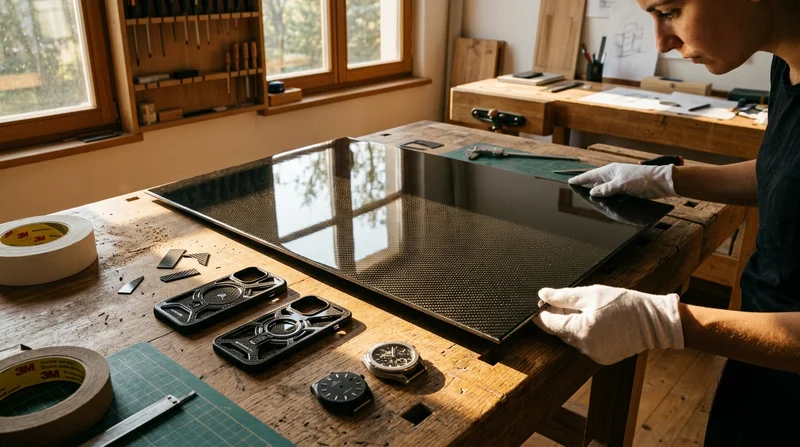
Carbon Fiber Plate — High-Gloss Decorative
High-gloss decorative carbon fiber plate with a mirror-like surface finish. The glossy coating enhances the visible 3K twill weave, creating a premium aesthetic for consumer-facing applications. Lightweight yet stiff, available in thin gauges for easy cutting and forming.
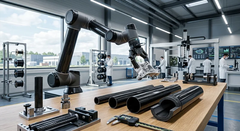
Carbon Fiber Robotic Arm Tube — High-Stiffness Lightweight Replacement
Precision-wound carbon fiber tubes for robotic arm links, replacing steel or aluminum in collaborative robots (cobots) and industrial manipulators. Achieve 3× the specific stiffness of aluminum with significant weight reduction, enabling faster acceleration and higher payload capacity.
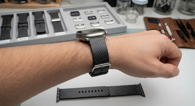
Carbon Fiber Watch Strap — 20mm/22mm Quick-Release
Premium carbon fiber watch strap with quick-release spring bars. Woven from T700 3K twill prepreg with a flexible resin system that conforms to the wrist. Available in 20mm and 22mm lug widths, compatible with Apple Watch, Samsung Galaxy Watch, Garmin, and traditional mechanical watches. Features a stainless steel buckle and carbon fiber keepers. The natural weave pattern makes each strap unique.