
A carbon fiber tube t-joint is one of the hardest joints to make in a lightweight structure, because a right-angle branch applies a bending moment to the main tube and carbon fibre is at its weakest when loaded across its fibres. A drone frame, robot arm, camera rig or chassis built from round tubes
Introduction
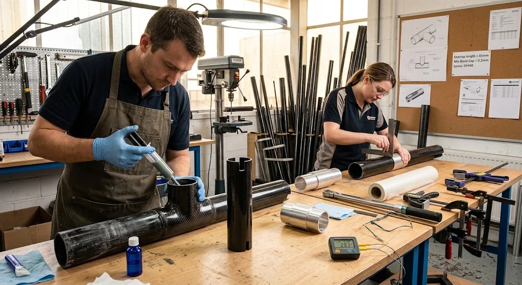
A carbon fiber tube t-joint is one of the hardest joints to make in a lightweight structure, because a right-angle branch applies a bending moment to the main tube and carbon fibre is at its weakest when loaded across its fibres. A drone frame, robot arm, camera rig or chassis built from round tubes nearly always needs t-joints where a vertical member meets a horizontal one, and the joint often decides the strength of the whole assembly. This guide explains what a carbon fiber tube t-joint must carry, compares the bonded, mechanical and hybrid ways to build one, and sets out the design rules that make a structural connection instead of a weak point.
The short answer is that a bonded or hybrid joint with a long, well-prepared interface beats a simple butt joint every time, and that the main tube must not be drilled or notched in a way that cuts its load-carrying fibres. The sections below show how to apply that principle and how to avoid the failures that show up later as cracks at the junction.
What a Carbon Fiber Tube T-Joint Must Carry
A t-joint transfers three kinds of load. The first is the bending moment from the branch: when a camera arm is loaded at its free end, the t-joint sees a moment that grows with the arm length, and the stress is highest exactly at the joint line. The second is torsion: a drone arm that resists yaw puts a twisting load on the branch tube. The third is the direct axial and shear load carried along the main tube past the junction. Carbon fibre handles all three well along the fibres, but the joint lets load cross between members, so the joint is where the laminate is loaded across its weakest direction. A t-joint therefore needs a large bonding or clamping area, not a small one, and the load must enter the joint gradually rather than at a sharp corner.
Bonded Carbon Fiber Tube T-Joint Options
Adhesive bonding is the lightest and often the strongest way to make a carbon fiber tube t-joint, because it spreads load over a long interface instead of concentrating it. Three bonded arrangements cover most cases.
- Notched seat with adhesive fillet: The branch tube is cut to match the main tube curvature, seated on the main tube, and bonded with a structural epoxy fillet. Simple and light, but the bond line is short and the joint carries only moderate loads.
- Bonded prefabricated T-fitting: A moulded carbon or glass-reinforced corner piece with two sockets is bonded over the end of the branch and onto the main tube. The fitting adds a long bonded surface in both directions, raising strength substantially.
- Bonded insert and connector: A machined aluminium or plastic connector with two sleeves is bonded into both tubes; one sleeve enters the branch, the other enters the main tube through a slot. This restores a near-continuous load path and is the strongest bonded option, at the cost of some weight.
The quality of the bond matters more than the geometry. Clean the surfaces, abrade them lightly, extend the bond length at least five tube wall thicknesses in each direction, and cure at the adhesive's specified temperature. A short, clean bond line beats a long one that is contaminated, because almost every premature failure starts at a poorly prepared surface.
Mechanical and Hybrid T-Joint Assembly
Mechanical assembly clamps or bolts the branch to the main tube, making the joint serviceable but adding weight and, in a bolted version, cutting into the tube. The table compares the main options for a drone-grade or robot-grade joint using 20-25 mm tubes.
| Method | Typical strength | Stiffness | Weight | Disassembly | Best for |
|---|---|---|---|---|---|
| Bonded notched seat | Moderate | Moderate | Low | No | Light frames, prototypes |
| Bonded T-fitting | High | High | Low-medium | No | Drone arms, gimbals |
| Bonded insert connector | Highest | Highest | Medium | No | Robot links, load-bearing frames |
| Clamp and bracket | Moderate-high | Moderate | Medium | Yes | Serviceable machines, demos |
| Bolted block | High | High | High | Yes | Chassis nodes, heavy duty |
The trade in the table is serviceability against weight and strength. A hybrid arrangement splits the difference: a bonded insert inside the branch takes the bending load, and carbon fiber tube clamps or a bolted bracket hold the insert so the joint can be opened. Because the bolt bears on the insert rather than the bare laminate, the wall is never crushed, which is the most common cause of t-joint failure in clamped designs. Where the joint must be taken apart regularly, the hybrid route is usually the best answer.
Carbon Fiber Tube Connection Design Rules
The same rules govern every carbon fiber tube connection inside a t-joint, and following them prevents the standard failure modes.
- Never let a bolt bear on bare laminate: Bond an insert or sleeve first, then clamp or bolt to the insert.
- Extend the interface: Make the bonded or clamped length at least three to five tube diameters along the main tube, so the load spreads instead of peaking at one point.
- Avoid sharp edge contacts: Radius every part edge that touches the tube; a sharp clamp edge acts like a knife and starts a crack under vibration.
- Route loads along fibres: Where a branch meets the main tube, load the fibres of both tubes in their length direction as much as the geometry allows.
- Seal exposed cut edges: Seal every machined end and slot with resin so moisture cannot enter the laminate and cause hidden delamination.
Follow these rules and the t-joint behaves like a structural node; ignore them and the junction becomes the crack that fails the whole assembly, usually at a moment when the part is loaded hardest.
How to Connect Carbon Fiber Tubes Without Crushing Them
Crushing is the most common failure of clamped carbon fiber tube connection work, and it is easy to avoid. The tube wall is strong in tension along the fibres but weak in the radial direction, so any screw, bolt or pointed clamp that presses directly on the wall will crush it. The practical answer is a bonded insert or a thin metal sleeve at every clamping point: the insert spreads the radial load into the wall thickness and gives a metal surface for the screw to bear on. Carbon fiber tube clamps with a wide, curved seat also spread the load over a large arc, and they should be sized so the clamp bore matches the tube outside diameter closely rather than a larger size padded with rubber. If a clamp must go directly on the bare tube, keep the contact area generous and use thread lock plus a torque limit instead of brute force. On thin-walled tubes, an insert is not optional; it is the difference between a joint and a crack.
Frequently Asked Questions
Is a bonded or a clamped carbon fiber tube t-joint stronger?
A well-made bonded joint is usually stronger, because it spreads the load over a long interface in both tube directions, and bonding the fibres in their strongest direction gives the best stiffness transfer. A clamped joint is easier to service but concentrates load at the clamp edge and can crush the wall if bolt torque is not controlled. The strongest practical arrangement is hybrid: bond an insert into the branch and main tubes, then clamp or bolt to the insert. That way the load path is continuous and the joint stays serviceable.
Can I drill a hole through a carbon fiber tube at a t-joint?
You can, but only if the hole is reinforced. A plain hole through the wall cuts the load-carrying fibres and creates a stress raiser that often becomes the start of a crack. If a through-bolt is unavoidable, bond a sleeve or insert into the tube before drilling, keep the hole sealed with resin, and size the bolt so the bearing stress at the hole stays within the laminate's limit. Where load is significant, prefer clamping to a bonded insert over drilling the bare tube.
How long should the bond overlap be at a carbon fiber tube t-joint?
As a rule of thumb, make the bonded overlap at least three tube diameters along the main tube and at least two diameters up the branch, and never less than five times the tube wall thickness in any direction. Longer overlaps transfer more load gradually and resist peeling, which is the failure mode of most bonded joints. The bond length is worth more than extra adhesive squeegeed into the joint, because strength comes from the interface area, not the fillet volume.
Conclusion
A carbon fiber tube t-joint carries a bending moment, torsion and axial load, and the best way to carry them is to spread load over a long, well-prepared interface instead of concentrating it at a corner. Bonded fittings and insert connectors are lightest and strongest, mechanical clamps and bolts are most serviceable, and a hybrid bond-and-clamp arrangement offers both. The design rules are short: never let a bolt bear on bare laminate, extend the interface, radius the edges, seal the cut ends, and support every clamp with an insert.
If you are building frames from carbon fiber tubes and need t-joint fittings, inserts, clamps and bonding guidance, browse our carbon fiber tube and connector range, or contact our engineering team for joint design support and matched hardware.
Part of topic
Related Articles
- Carbon Fiber Tubes and Rods: Sizing and Selection for Projects
- Carbon Fiber Tube Chassis: Space Frames for Vehicles and Drones
- Carbon Fiber Tube Connect: Complete Assembly Guide
- Carbon Fiber Tube Connection: Sleeves, Inserts and Adhesive Joints
- Carbon Fiber Tube Clamps: Joint Design and Hardware Selection
- Carbon Fiber Sheets for Sale 1mm: Grade and Thickness Buying Guide
Interested in Our Products?
Contact our team for competitive pricing and technical specifications.
Get a QuoteRelated Products

Carbon Fiber Plate — 3K Twill T700 1.5mm
Thin 1.5mm carbon fiber plate with 3K twill weave surface. Lightweight and stiff, commonly used for covers, panels, drone bodies, and applications requiring a premium aesthetic appearance.

Carbon Fiber Plate — 3K Twill T700 3.0mm
Medium-thickness 3.0mm carbon fiber plate offering significantly higher load capacity while maintaining attractive 3K twill finish. Suitable for structural brackets, reinforcement plates, and load-bearing panels.

Square Carbon Fiber Tube — 3K Twill T700
Square cross-section carbon fiber tube manufactured with 3K twill weave for torsional strength. Preferred for structural frames, trusses, and support columns where rectangular geometry offers design flexibility.

Round Carbon Fiber Tube — UD Unidirectional T700
Unidirectional (UD) round tube with all fibers aligned axially for maximum longitudinal stiffness. Ideal for applications requiring high bending rigidity with minimal weight, such as shafts, struts, and structural reinforcements.
Round Carbon Fiber Tube — 3K Plain Weave T700
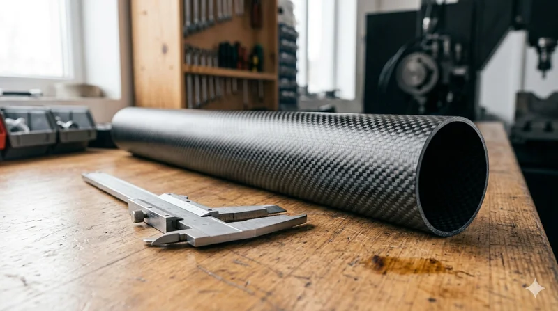
Standard round carbon fiber tube manufactured from Toray T700 grade fiber with 3K plain weave. Offers balanced strength and stiffness for general industrial applications including robotics, automation, sports equipment, and aerospace structures.