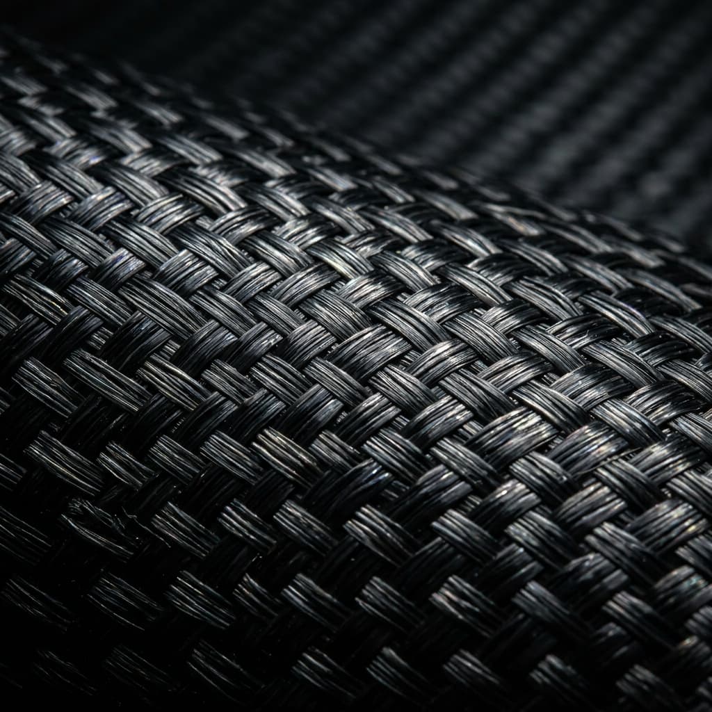
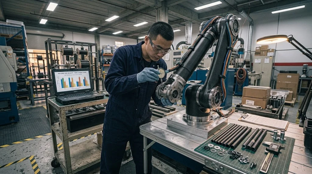
A carbon fiber robot arm is not a cosmetic upgrade — it is a change to every number in the motion profile. Cutting segment mass lowers inertia at the joint, which lets the same servo accelerate faster or carry more payload for the same current draw. The savings are real, but so are the tradeoffs: jo
Introduction
A carbon fiber robot arm is not a cosmetic upgrade — it is a change to every number in the motion profile. Cutting segment mass lowers inertia at the joint, which lets the same servo accelerate faster or carry more payload for the same current draw. The savings are real, but so are the tradeoffs: joints behave differently, thermal expansion no longer matches aluminum tooling, and a structure that was designed isotropic now has a grain direction that must be respected.
This article walks through the lightweight design tradeoffs of a carbon fiber robot arm — inertia versus stiffness, joint and bearing design, where a carbon fiber rod or a pultruded carbon fiber rod belongs in the assembly, plus damping, isolation from galvanic corrosion, and the cost math that decides whether the swap pays back.
Carbon Fiber Robot Arm: Where the Mass Savings Land
Robot arms accelerate their own structure before they accelerate payload. For a joint driven through a gearbox, reflected inertia at the motor scales with the mass of everything downstream of the gear, so removing one kilogram from a forearm can be worth several kilograms at the shoulder. Carbon segments at 1.6 g/cm³ replace aluminum at 2.7 g/cm³ and steel at 7.85 g/cm³, and because specific stiffness is also higher, the wall section can stay thin without giving up deflection targets.
| Metric | Aluminum arm segment | Carbon fiber arm segment | Design consequence |
|---|---|---|---|
| Density | 2.70 g/cm³ | 1.55-1.65 g/cm³ | 40% mass cut at equal external size |
| Elastic modulus (directional) | 69 GPa, isotropic | 120-160 GPa axial, laminate dependent | Deflection drops if plies run along the beam axis |
| Specific stiffness | ~26 kNm/kg | ~75-95 kNm/kg | Thinner walls reach the same stiffness target |
| Arm inertia at shoulder (relative) | 1.0 (baseline) | 0.45-0.6 | Higher acceleration or smaller servo for the same move |
| Thermal expansion | 23 µm/m·K | 0.5-2 µm/m·K along fiber | Warm-cell repeatability shifts against aluminum frames |
| Relative segment cost | 1x | 4-8x | Justify by cycle time, payload or reach, not grams alone |
The honest reading of that table: mass reduction alone rarely pays for the arm. The business case appears when inertia savings translate into shorter cycle time, when a smaller motor and drive handle the same payload, or when a longer reach fits inside the same envelope without increasing gearbox loads.
Design Tradeoffs: Stiffness, Damping and Joint Stiffness
Weight is the headline, but robot accuracy is decided by the structure's stiffness chain and its vibration decay. A carbon segment is very stiff per gram along the fiber and softer off-axis, so a tube laid up with all-axial plies can be light yet twist-prone; adding ±45° layers costs a few percent of mass and buys torsional rigidity where the wrist rotates.
- Joint interfaces: bolted flanges into carbon laminate need compression pads or through-ply metal inserts — point-loading a laminate with a bare bolt crushes resin and loosens over cycles.
- Damping: CFRP damps less than aluminum at the laminate level, so a very light arm can ring after a fast stop; solve it with a viscoelastic layer at the joint or slightly conservative deceleration ramps, not by adding mass back everywhere.
- Deflection budget: size the section against deflection at full extension first, inertia second — arms that pass the inertia target but sag 0.5 mm at the tool lose the accuracy the upgrade was meant to buy.
- Bearing seats: press-fit bearings in carbon need a bonded or shrunk metal sleeve; the laminate will creep under sustained line load where aluminum would not.
Thermal mismatch deserves its own note: a carbon arm in a warm cell grows almost nothing while the aluminum frame grows about 0.23 mm per meter per 10 °C. On long-reach arms that offset shows up as tool-position drift through the shift — calibrate cold, or meter the cell.
Carbon Fiber Rod and Pultruded Carbon Fiber Rod in the Assembly
Not every part of a robot needs a wound tube. Cable management channels, light end-effector frames, encoder shields and gripper fingers are natural work for stock sections — which is where a carbon fiber rod enters the bill of materials. Solid pultruded rod is cheap, straight and axially stiff, ideal for fingers, pins and light linkages; roll-wrapped rod sections hold tighter diameter for pivot fits.
- Use carbon fiber rod for: gripper jaws, dowel alignment pins, lightweight cross-members and sensor mounting posts, where loads are modest and axial.
- Specify pultruded carbon fiber rod by: diameter tolerance (±0.1 mm typical), length, and end finish — chamfered ends keep the rod from digging into its seat over vibration cycles.
- Isolate from aluminum mounts: carbon is cathodic; nylon or PEEK washers and a sleeve at the interface prevent galvanic corrosion in washdown or humid cells.
- Watch the failure mode: rod breaks without yielding. Keep working stress conservative or design the gripper so a failed rod cannot drop the part.
Cabling is the fourth place mass hides. P-clips anchored to carbon must not clamp sharp: route harnesses through bonded eyelets or rubber-lined channels, because a chafing bundle on a vibrating carbon edge is a classic first-year failure.
Frequently Asked Questions
How much payload does a carbon fiber robot arm add?
For a typical six-axis arm, replacing aluminum forearm and upper-arm structures with CFRP cuts moving mass enough to raise effective payload roughly 15-25% at the same motors, or to shorten move times by a similar margin. The exact figure depends on how much of the original mass was structural rather than motors, cables and castings.
Is a carbon fiber robot arm worth the cost for small shops?
Only when the constraint is cycle time, reach or payload — never for rigidity alone, since a well-designed aluminum arm can be stiffer per euro. Shops running three shifts with tight takt time usually see payback inside a year; occasional-use machines rarely do.
How do you join carbon arm segments to aluminum gearboxes?
Use a flat bonded flange with a full-face compression pad, adhesive qualified for the surface preparation, and stainless or aluminum fasteners with an isolation layer at the interface. Avoid countersunk bolts pulling directly into laminate, and torque in a star pattern to spread clamp load evenly across the flange.
Conclusion
A carbon fiber robot arm earns its place when lower inertia converts into real throughput or payload, and when the design respects the tradeoffs: joint compression, torsional plies, damping, thermal mismatch and galvanic isolation. Handle those and the lighter arm is also the more accurate one.
YongXian supplies roll-wrapped and pultruded carbon fiber tube, plate and rod for robot arm structures and end effectors. Browse our carbon fiber rod and tube range or contact our engineering team with your drawing and target quantity.
Part of topic
Related Articles
- Carbon Fiber License Plate Custom Guide: Frames That Fit and Last
- Building Carbon Fiber Drone Frames: Layout and Fastening
- Carbon Fiber Tube for Drone Frames: Sizing and Wall Selection
- Carbon Fiber Plates for Running Shoes: How They Work
- Carbon Fiber Plate for Foot Orthotics: Design and Materials
- Carbon Fiber Drone: When Composite Airframes Make Sense
Interested in Our Products?
Contact our team for competitive pricing and technical specifications.
Get a QuoteRelated Products
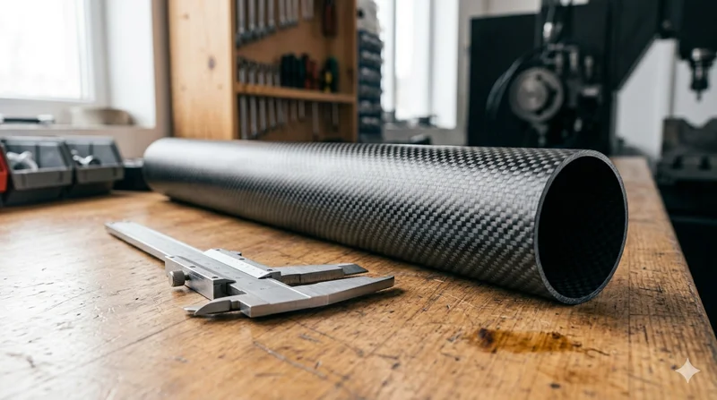
Round Carbon Fiber Tube — 3K Plain Weave T700
Standard round carbon fiber tube manufactured from Toray T700 grade fiber with 3K plain weave. Offers balanced strength and stiffness for general industrial applications including robotics, automation, sports equipment, and aerospace structures.
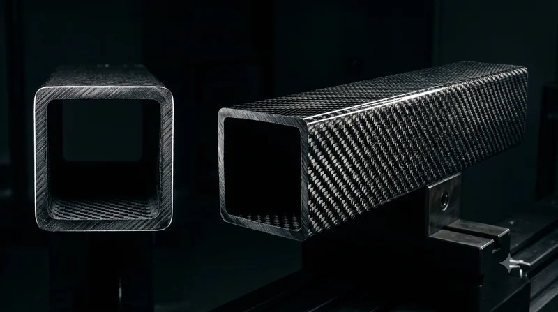
Square Carbon Fiber Tube — 3K Twill T700
Square cross-section carbon fiber tube manufactured with 3K twill weave for torsional strength. Preferred for structural frames, trusses, and support columns where rectangular geometry offers design flexibility.
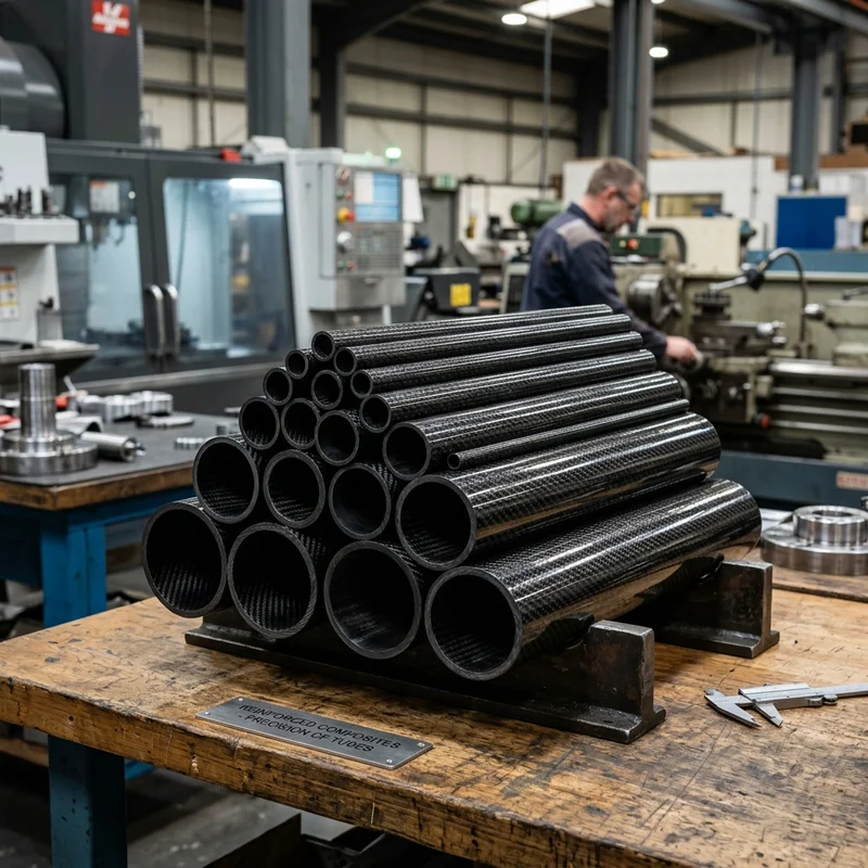
Round Carbon Fiber Tube — 3K Twill
Lightweight and ultra-stiff round tubes ideal for drone frames, robotics, and structural applications.
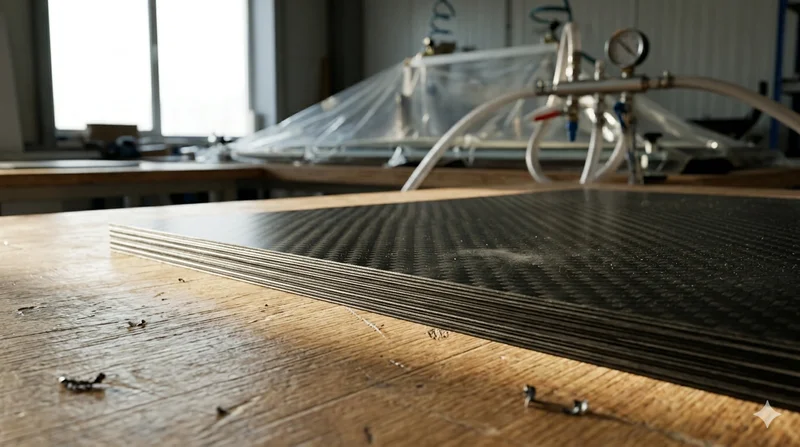
Carbon Fiber Plate — 3K Twill T700 3.0mm
Medium-thickness 3.0mm carbon fiber plate offering significantly higher load capacity while maintaining attractive 3K twill finish. Suitable for structural brackets, reinforcement plates, and load-bearing panels.
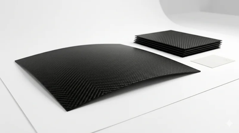
Carbon Fiber Plate — 3K Twill T700 1.5mm
Thin 1.5mm carbon fiber plate with 3K twill weave surface. Lightweight and stiff, commonly used for covers, panels, drone bodies, and applications requiring a premium aesthetic appearance.