
Carbon fiber control arms are one of the most demanding composite applications in the automotive industry, because a control arm is not a fairing or a cosmetic panel: it is a safety-critical structural link that carries braking, cornering, and pothole impact loads for the life of the vehicle. When a
Introduction
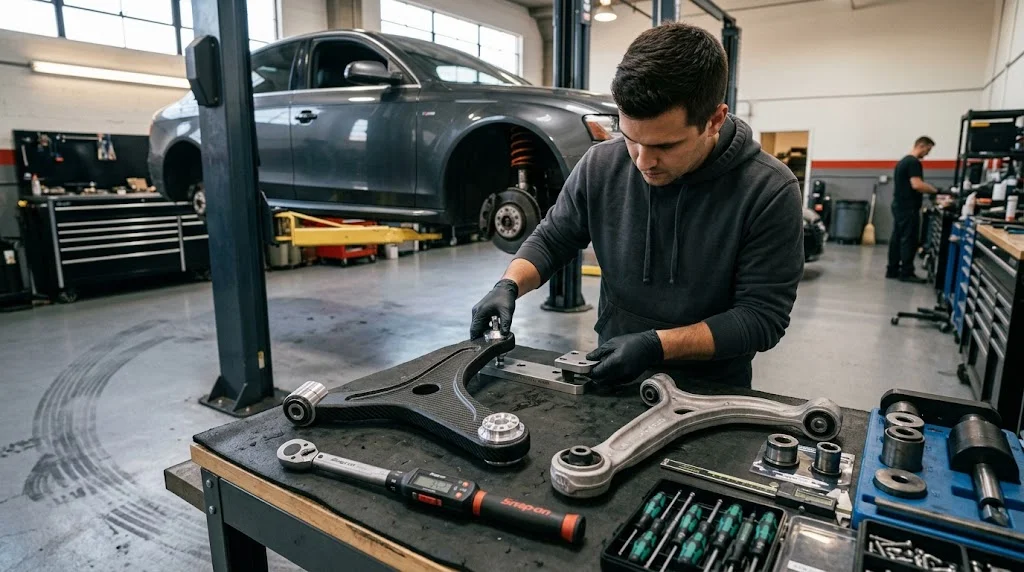
Carbon fiber control arms are one of the most demanding composite applications in the automotive industry, because a control arm is not a fairing or a cosmetic panel: it is a safety-critical structural link that carries braking, cornering, and pothole impact loads for the life of the vehicle. When a chassis team specifies carbon fiber control arms, the goal is almost always unsprung mass reduction, but the real engineering work happens at the interfaces: where the bushings press in, where the ball joint bolts on, and how the laminate handles the multi-axis fatigue spectrum of real roads.
This article explains why OEMs and aftermarket builders are moving control arms into carbon fiber auto parts programs, how suspension geometry constrains the design, and what buyers should demand from a supplier of carbon fiber car parts before committing to a tooling program.
Why Unsprung Mass Drives Carbon Fiber Control Arms
Unsprung mass, everything below the spring, directly affects ride, grip, and impact response. A conventional forged aluminum front control arm on a mid-size passenger car weighs 2.5 to 4.0 kg per side; a steel stamping of the same part weighs 4.5 to 6.5 kg. A carbon fiber control arm of equivalent stiffness and strength typically lands at 1.2 to 2.2 kg, a 40 to 55 percent reduction against aluminum and 60 to 70 percent against steel.
Vehicle dynamics teams generally treat a 1 kg unsprung reduction as worth 2 to 4 kg of sprung mass in ride-quality terms, which is why composite control arms appear first on performance and luxury programs, then trickle into electric vehicles where every kilogram extends range. Reducing the mass the spring must control also lowers the energy transmitted through the bushing stack on sharp impacts, reducing cabin intrusion noise and extending bushing life.
Control Arm Material Comparison
The table below compares the main material routes for a typical lower control arm, using a mid-size passenger car front arm as the reference part.
| Property | CFRP (Prepreg, T700) | Forged Aluminum 6061-T6 | Steel Stamping | Glass Fiber SMC |
|---|---|---|---|---|
| Density (g/cm³) | 1.55-1.60 | 2.70 | 7.85 | 1.85-1.95 |
| Tensile modulus (GPa) | 120-140 (UD) | 69 | 200-210 | 10-14 |
| Specific stiffness (GPa/(g/cm³)) | 75-90 | 26 | 26-27 | 5-8 |
| Arm weight (kg) | 1.2-2.2 | 2.5-4.0 | 4.5-6.5 | 2.0-3.2 |
| Fatigue capability | Excellent (10⁷ cycles) | Good | Excellent | Poor in tension-tension |
| Corrosion resistance | Excellent | Good (anodized) | Requires coating | Excellent |
| Relative piece cost (index) | 3.5-6x | 1.4-1.8x | 1.0x | 1.2-1.5x |
| Tooling investment | High | High (forging dies) | Medium | Medium |
Carbon fiber wins the mass and specific-stiffness columns decisively, which is why the material appears in carbon fiber body parts programs as well: once a program has validated composite structural parts, doors, hatch frames, and control arms can share testing infrastructure.
Suspension Geometry Constraints on Composite Design
A control arm must hold its hardpoints within tight tolerance across temperature, load, and life. That shapes the composite design in several specific ways.
- Bushing interfaces: Rubber or hydraulic bushings are pressed or bonded into metallic cups. In a CFRP arm, the cup is a machined aluminum or steel insert co-cured or bonded into the laminate, with the bearing length and press-fit diameter designed so the insert carries hoop stress and the laminate carries axial load.
- Ball joint mounts: Ball joint housings see point loads and torque during installation. Designers use local doubler plies, woven face sheets, and metal load-spreading plates rather than allowing fasteners to bear directly on unidirectional laminate.
- Stacking and kinematics: The arm's bending axis, bushing eccentricity, and camber change under load must match the steel or aluminum original exactly. Composite creep under sustained preload is managed with conservative fiber angles (0-degree fraction above 55 percent) and by keeping bolted joints out of high-stress laminate zones.
- Crash and impact loads: Control arms see overload events from kerb strikes and potholes. CFRP tolerates these through progressive microcracking rather than yielding, so designs are validated with 2.5x design-load static tests and 10⁷-cycle fatigue at 60 percent of peak operating load.
Layup and Manufacturing Routes
Two production routes dominate carbon fiber control arm manufacturing today. Prepreg autoclave layup remains the choice for low-volume performance programs: hand-laid unidirectional plies with woven scrims at inserts, cured at 120-180 C, delivering the highest fiber volume fraction (58-62 percent) and the most consistent fatigue performance. Cycle times of 2-4 hours per batch limit this route to flagship vehicles and aftermarket arms.
For volume production, compression-molded sheet molding compound with 40-50 percent long chopped fiber, or hybrid layups of continuous UD tapes in a compression mold, reduce cycle time to 3-6 minutes per part. The trade is a 10-20 percent stiffness penalty versus autoclave prepreg, usually absorbed by a slightly thicker section. Metal inserts are placed in the mold before closing, so the finished arm emerges with bushing cups and ball joint plates already integrated.
Frequently Asked Questions
Are carbon fiber control arms safe for street use?
Yes, when they are designed and validated to automotive standards. A properly engineered carbon fiber control arm is tested to static overload at 2.5 times the design load, fatigue to 10 million cycles at 60 percent of peak operating load, and environmental conditioning including thermal cycling, salt spray, and stone impact. The failure mode of CFRP under overload is progressive and detectable in service inspections, unlike the sudden yielding of an under-designed aluminum arm. Reputable suppliers provide the test report and laminate specification with each production batch.
How much unsprung mass does a full set of carbon fiber control arms remove?
A typical mid-size car has four to six control arms. Replacing forged aluminum arms with CFRP versions removes roughly 5 to 9 kg of unsprung mass in total; replacing steel arms removes 12 to 20 kg. In dynamics terms, that is equivalent to a 15 to 40 kg reduction in sprung mass for ride quality, and it also reduces the momentum the spring and damper must control on sharp impacts, which shows up as better transient response and reduced impact harshness in NVH testing.
Can carbon fiber control arms be repaired after an impact?
Structural repair is generally not recommended for safety-critical suspension parts. Microcracking from a kerb strike can be invisible externally while reducing residual strength. The correct procedure is replacement. What can be maintained is the interface hardware: bushing cups, ball joint plates, and fasteners are metallic and replaceable, so a service kit restores the connection without disturbing the laminate. Store spare arms away from UV exposure and solvents, and inspect the laminate surface annually for deep scratches that reach the first ply.
Conclusion
Carbon fiber control arms deliver the largest practical unsprung mass reduction available to a chassis program today, but the material is only half the work. The other half is interface design: metal inserts for bushings and ball joints, layups that manage multi-axis fatigue, and manufacturing routes matched to program volume. That combination of composite design discipline and automotive validation is exactly what YongXian brings to carbon fiber car parts programs. Explore our carbon fiber sheet and plate range for arm layups and insert backing, or contact our engineering team to discuss control arm prototypes, laminate specifications, and validation support for your next suspension program.
Part of topic
Related Articles
- Carbon Fiber Tube Cap: End Fittings and Sealing Solutions
- Carbon Fiber Plate in Shoes: Running, Cycling and Everyday Footwear
- Carbon Fiber Drone Frame: Selection Guide for Racing and Industrial Drones
- Carbon Fiber Plate with Morton's Extension: Metatarsal Support in Footwear
- Carbon Fiber Road Bike Wheels: Rim Profile and Spoke Choice
- S500 Carbon Fiber Quadcopter Drone Frame Kit: Specifications and Upgrades
Interested in Our Products?
Contact our team for competitive pricing and technical specifications.
Get a QuoteRelated Products

Carbon Fiber Plate — 3K Twill T700 1.5mm
Thin 1.5mm carbon fiber plate with 3K twill weave surface. Lightweight and stiff, commonly used for covers, panels, drone bodies, and applications requiring a premium aesthetic appearance.

Carbon Fiber Plate — 3K Twill T700 3.0mm
Medium-thickness 3.0mm carbon fiber plate offering significantly higher load capacity while maintaining attractive 3K twill finish. Suitable for structural brackets, reinforcement plates, and load-bearing panels.

Square Carbon Fiber Tube — 3K Twill T700
Square cross-section carbon fiber tube manufactured with 3K twill weave for torsional strength. Preferred for structural frames, trusses, and support columns where rectangular geometry offers design flexibility.

Round Carbon Fiber Tube — UD Unidirectional T700
Unidirectional (UD) round tube with all fibers aligned axially for maximum longitudinal stiffness. Ideal for applications requiring high bending rigidity with minimal weight, such as shafts, struts, and structural reinforcements.
Round Carbon Fiber Tube — 3K Plain Weave T700
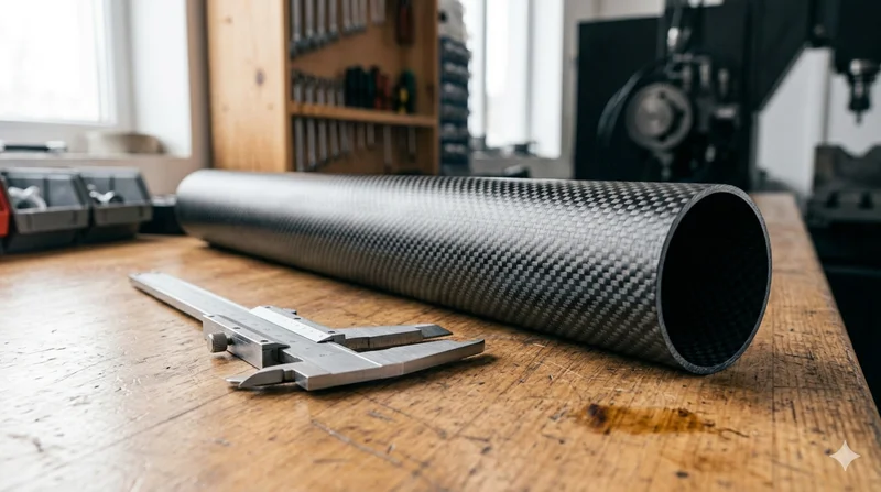
Standard round carbon fiber tube manufactured from Toray T700 grade fiber with 3K plain weave. Offers balanced strength and stiffness for general industrial applications including robotics, automation, sports equipment, and aerospace structures.