
The root joint is the single most heavily loaded connection in a wind turbine blade. Every bending moment and shear load generated along the blade converges at the root, where the blade must transfer them into the hub through a circular array of bolted connections. In a modern large bla
Introduction
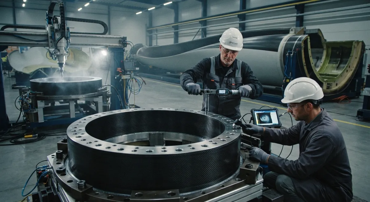
The root joint is the single most heavily loaded connection in a wind turbine blade. Every bending moment and shear load generated along the blade converges at the root, where the blade must transfer them into the hub through a circular array of bolted connections. In a modern large blade this array can contain several hundred bolts, and a failure in any one of them is a serious structural event. The design of this joint has become more demanding as blades have grown, spar caps have moved to carbon fiber, and loads have increased.
Two bolted root joint architectures dominate the industry: the T-bolt or post-bonded connection, and the stud or T-nut connection. Both have been used across thousands of blades, but their engineering trade-offs are different, and the balance changes when the spar cap is made of carbon fiber. This article explains how each design transfers load, compares their fatigue and manufacturing behavior, and provides guidance for blade designers choosing between them in the era of large carbon spar caps.
How the Root Joint Transfers Load
The root of a modern blade is typically an annular band built from the continuous laminate of the spar cap and shell, machined to a circular profile with a mating flange. Bolts arranged around the circumference pass through this band into a steel root insert or into a steel T-nut seated behind a reinforcing laminate. The flange face of the blade bolts directly to the blade bearing and hub. Because the joint must be disassembled for transport and maintenance, the connection is almost always mechanical — bolted — rather than bonded, since a bonded root cannot be separated in the field.
The load path differs between the two designs. In a T-bolt connection, a steel barrel with a transverse steel pin (the "T") is bonded into a slot machined in the root laminate; the bolt engages the pin, and preload compresses the laminate between the pin and the flange. In a stud or T-nut connection, a threaded stud passes through the laminates and into a steel T-nut embedded behind the shell, or into a machined root plate. The choice affects where the clamping force is concentrated and how fatigue loads are distributed through the laminate thickness.
T-Bolt (Post-Bonded) Connection
The T-bolt connection, also called the post-bonded root, is one of the most widely used designs for small to medium blades. A straight cylindrical barrel is bonded into a machined radial slot near the root; the barrel carries a transverse steel pin. The bolt passes radially and engages the pin, so when the bolt is tightened, the clamping force compresses the laminate between the pin and the blade flange. This distributes load through a relatively long portion of the laminate, reducing peak bearing stresses at the hole.
The principal advantages of the T-bolt are tolerance for slight misalignment, effective load spreading through the bonded barrel, and a compact, replaceable connection. The main drawbacks are the additional machining of the root band and the higher cost of the barrel and pin hardware. In fatigue, the T-bolt distributes load more uniformly through the laminate thickness, which is favorable where the root laminate is thick and load concentration is a concern.
Stud (T-Nut) Connection
The stud or T-nut connection uses a longer threaded stud that passes through the root laminate and engages a steel T-nut seated behind the reinforcing laminate, or a machined steel root disc. The stud is tensioned from the outside, pulling the nut against the back face. Because the stud is essentially a hardened steel bolt embedded in the laminate stack, the load path runs the full thickness of the root band and the bearing load is carried directly by the T-nut.
Stud connections are generally lower-cost in small blades and allow a slightly shallower root envelope, which can benefit blade geometry. Their main limitation involves fatigue and load distribution: the clamping force is concentrated at the T-nut behind the laminate, and in thick or low-strength laminates this can create higher peak stresses and greater sensitivity to local voids or manufacturing defects. In larger blades and thicker carbon spar caps, bearing stress at the T-nut seat and the interaction with fatigue become more critical design factors.
Comparison in Large Carbon Spar Caps
As spar caps transition to carbon fiber for blades over roughly 80 meters, the root joint trade-offs change in three ways:
- Through-thickness strength: Carbon laminates are stiffer and stronger in-plane but have lower through-thickness strength than thick glass/epoxy laminates, so designs that concentrate bearing load on the laminate face become less favorable.
- Thinner root section: Carbon spar caps are typically shallower and thinner at the root to save weight, leaving less laminate thickness to distribute the clamping load.
- Hole sensitivity: Carbon is more sensitive to bolt-hole stress concentrations and to local crushing from high bearing loads, so load-spreading architectures tend to be preferred.
The table below summarizes the trade-offs:
| Factor | T-Bolt (Post-Bonded) | Stud (T-Nut) | Best Choice for Large Carbon Spar Caps |
|---|---|---|---|
| Laminate machining at root | Radial slot machined | Less machining, through holes | Depends on process |
| Load spread through laminate thickness | Distributed over longer length | Concentrated at T-nut seat | T-Bolt favored |
| Peak bearing stress at hole | Lower, spread by barrel | Higher, concentrated | T-Bolt favored |
| Hardware cost | Higher (barrel + pin) | Lower | Stud favored |
| Root envelope depth | Slightly deeper | Shallower | Stud favored |
| Fatigue under high bending moment | More uniform distribution | More sensitive to defects | T-Bolt favored |
| Through-thickness strength requirement | Lower, load spread | Higher, bearing at back face | T-Bolt favored |
The pattern is consistent: as carbon spar caps grow, the load-spreading and fatigue advantages of the T-bolt become more valuable, while the cost and envelope advantages of the stud connection diminish in relative importance. This is why the largest blades increasingly rely on post-bonded or T-bolt type architectures, or hybrid approaches that spread bearing load over a greater laminate volume.
Manufacturing and Fatigue Considerations
The choice between T-bolt and stud also affects manufacturing and quality assurance. T-bolt slots must be machined accurately into the cured laminate and the barrel bonded with a controlled adhesive layer; any gap or void in the bond line directly reduces load transfer and increases fatigue risk. Stud connections rely on accurate hole drilling and consistent torque application, with the T-nut seated firmly behind the laminate. Non-destructive testing is used at the root in both cases — ultrasound around the bonded barrel or T-nut seat, and bolt load verification through torque or ultrasonic elongation measurement.
Fatigue is governed by the combination of bolt preload, the alternating bending moments from wind loads, and how well the compression load is distributed. Adequate preload keeps the joint in compression through the load cycle, preventing fretting and load reversal. For carbon spar caps, the design must also verify that local bearing stresses at the hole and the T-nut seat stay within the laminate's through-thickness allowables, which are lower than in thick glass/epoxy sections. Sealing the joint against moisture ingress is another consideration, since water in the root can accelerate galvanic corrosion between carbon and steel hardware.
Frequently Asked Questions
Why is the blade root joint bolted rather than bonded?
The root joint must be demountable for transport, blade replacement, and maintenance, so a mechanical connection is required. Blades are transported separately and assembled on site with the hub, and operators may need to remove individual blades for service or repair. A bonded root joint, which cannot be separated in the field without destroying the joint, would make these operations impossible. Bolted connections also allow individual bolts to be inspected, re-tensioned, or replaced without affecting the rest of the joint, which is important for long-term serviceability of large blades.
What is the main failure mode of blade root joints?
The most common and critical failure mode is root bolt fatigue, driven by the high alternating bending moments at the root under wind loading. When preload is inadequate or load distribution concentrates stress, bolts can crack over many load cycles. A second important failure mode is bearing or crushing failure of the laminate at the bolt hole or T-nut seat, particularly in carbon fiber laminates which have lower through-thickness and bearing strength than thick glass/epoxy sections. Fretting corrosion at the steel-carbon interface is a related long-term concern that proper sealing and preload management mitigate.
How does carbon fiber change the root joint design compared to glass?
Carbon fiber has higher in-plane stiffness and strength but lower through-thickness and bearing strength than thick glass/epoxy laminates, so the root joint must spread load more carefully. Carbon spar caps are also thinner at the root for weight reasons, providing less laminate volume to distribute the clamping load. As a result, load-spreading architectures such as the T-bolt or post-bonded connection, which distribute load over a longer portion of the laminate, tend to be favored for large carbon spar caps. The design must also verify local stresses stay within carbon's lower through-thickness allowables and manage galvanic corrosion between carbon and steel.
What should blade designers consider when selecting a root joint design?
The primary considerations are the magnitude of the alternating bending moment, the thickness and through-thickness strength of the root laminate, manufacturing and cost targets, and fatigue life requirements. For small blades with thick glass laminates and tight cost targets, stud connections are often adequate. As blades grow, carbon spar caps appear, and fatigue loads increase, the load-spreading and fatigue advantages of the T-bolt favor its use despite higher hardware cost. The decision is ultimately an optimization across load, cost, weight, and manufacturing, verified by full-scale root section testing.
Conclusion
The bolted root joint is the critical interface where the entire aerodynamic load of a wind blade is transferred to the hub, and its design must balance load transfer, fatigue, manufacturing, and cost. The T-bolt and stud connections both have long service records, but their trade-offs shift as blades grow and spar caps move to carbon. The load-spreading behavior and fatigue performance of the post-bonded T-bolt become increasingly valuable in large carbon spar caps, where through-thickness and bearing strength are the governing constraints.
For blade engineering teams, the practical path is to model the root joint load path, verify bearing and fatigue margins against carbon laminate allowables, and validate the chosen architecture with root section fatigue testing. Explore our carbon fiber spar cap and structural reinforcement materials, or contact our engineering team to discuss root joint design and material selection for your blade program.
Part of topic
Related Articles
- Bio-Based Carbon Fiber Precursors: Lignin and Polyethylene for Low-Cost Production
- Large-Tow Carbon Fiber Cost Analysis: 48K vs 60K Price-Performance Comparison
- Carbon Fiber-Resin Interface Bonding: Surface Treatment and Coupling Agent Optimization
- Digital Twin for Carbon Fiber Manufacturing: Real-Time Process Monitoring and Defect Prevention
- Thermoplastic Carbon Fiber Welding for Automotive: Ultrasonic and Induction Welding Process Windows
- Large-Tow Carbon Fiber Wet Spinning: Process Optimization for 48K/60K Production Efficiency
Interested in Our Products?
Contact our team for competitive pricing and technical specifications.
Get a QuoteRelated Products

Carbon Fiber Fishing Rod Blank
High-quality carbon fiber fishing rod blank manufactured from multiple grades of Toray carbon fiber cloth. Available in a wide range of lengths, powers, and actions for freshwater and saltwater applications. Suitable for OEM rod building.

Custom Carbon Fiber Medical Device Components
Medical-grade carbon fiber components manufactured for imaging equipment, surgical instruments, and patient support systems. Carbon fiber's radiolucency (X-ray transparency) and high strength-to-weight ratio make it ideal for CT scanner beds, wheelchair frames, surgical robot arms, and MRI-compatible accessories. Biocompatible resin systems available.

Square Carbon Fiber Tube — 3K Twill T700
Square cross-section carbon fiber tube manufactured with 3K twill weave for torsional strength. Preferred for structural frames, trusses, and support columns where rectangular geometry offers design flexibility.

Carbon Fiber Plate — UD Unidirectional T700
Unidirectional carbon fiber plate with all fibers oriented in a single direction for maximum strength along the fiber axis. Essential for structural reinforcements, splints, and applications where load direction is predictable.
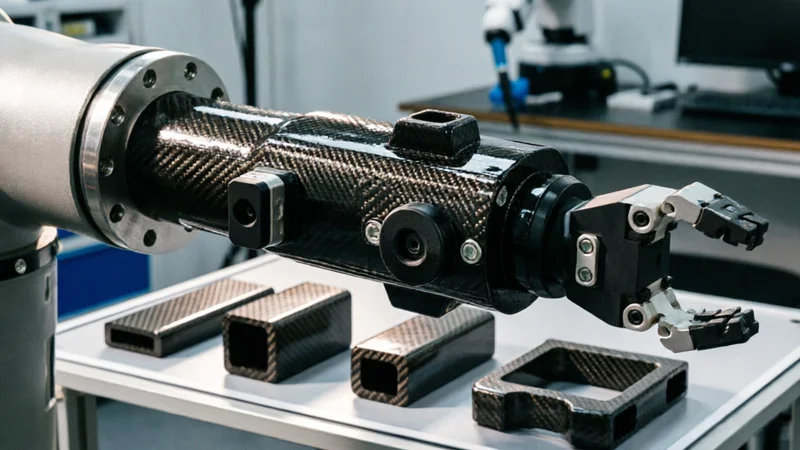
Carbon Fiber Robot End Effector Link — Custom Shape & Sensor Integration
Custom-shaped carbon fiber end effector links for robotic arms. Designed for automation integrators and research labs requiring lightweight, rigid connections between the robot wrist and gripper/tool. Can incorporate sensor mounting bosses, cable routing channels, and quick-change interfaces.