
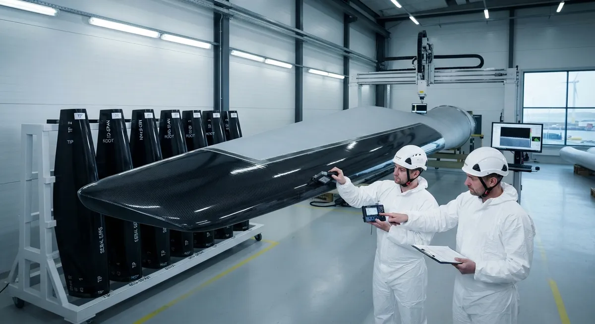
Technical analysis of wind turbine blade leading edge erosion and carbon fiber LEP systems: erosion mechanisms at 85-95 m/s tip speed, CFRP LEP material architecture with 120-180 minute DNV-RP-0573 rain erosion resistance vs 35-55 minutes for PU, surface roughness Ra 3-8 µm vs 25-50 µm over 18 months offshore, cost comparison EUR 8,000-15,000 per blade for CFRP vs EUR 2,000-4,000 for PU coating, and certification requirements.
Wind Blade Leading Edge Erosion: Why Carbon Fiber Protection Is the 2026 Standard
Leading edge erosion (LEE) of wind turbine blades has emerged as one of the most costly operational challenges in the wind energy sector. A single eroded blade leading edge can reduce annual energy production (AEP) by 3–8%, and in offshore Class I wind sites (annual average wind speed 8.5–10 m/s at hub height), blade tip speeds reaching 85–95 m/s accelerate erosion rates dramatically. Globally, blade repair and replacement due to leading edge erosion accounts for an estimated EUR 580–720 million annually in direct maintenance costs, with lost energy production adding EUR 340–450 million in indirect costs. For a typical 5 MW offshore turbine, a single leading edge erosion repair can cost EUR 35,000–60,000 in direct labor, materials, and crane mobilisation, plus EUR 15,000–25,000 in lost production during the 48–72 hour downtime window.
In response, wind farm operators and blade OEMs increasingly specify carbon fiber reinforced polymer (CFRP) leading edge protection (LEP) systems as the baseline standard for new blade designs and major retrofits. The global wind blade LEP market, valued at USD 280 million in 2024, is projected to reach USD 540 million by 2029 at a CAGR of 14.0%, with CFRP-based systems accounting for an increasing share of new installations — projected to reach 38% of offshore new-builds and 22% of onshore new-builds by 2027.
Erosion Mechanisms at Blade Tip Speeds
Leading edge erosion on wind turbine blades is driven by three primary mechanisms that degrade the blade surface over time. Understanding these failure modes is essential to specifying the correct LEP material system:
- Rain droplet impact erosion: At blade tip speeds of 85–95 m/s, a 3 mm diameter raindrop impacts the leading edge with a kinetic energy of approximately 3.5 J, generating instantaneous compressive stresses exceeding 500 MPa at the point of contact. The repetitive impact — at typical rainfall rates of 500–2,000 drops/m²/second — progressively fatigues the surface, starting as micro-cracking at the gelcoat surface (typically within 3–6 months of operation in moderate rainfall zones), extending to pitting at 12–18 months, and ultimately to full coating delamination by 24–36 months. Offshore sites in the North Sea and Baltic Sea, with 180–220 rainy days per year and average rainfall intensity of 3.5 mm/hour, experience the most aggressive erosion rates globally.
- Hail and solid particle impact: Hailstones with diameters of 10–50 mm (typical for mid-latitude wind sites) deliver impact energies of 5–80 J. While CFRP-based LEP systems can withstand hailstones up to 25 mm at tip speed without visible damage, unprotected gelcoat begins to spall at 15 mm hailstone diameter. Sand and dust abrasion in arid wind sites (Mojave Desert, Gobi Desert, Patagonian steppe) adds a continuous low-energy erosion component that synergises with rain erosion, accelerating the transition from micro-cracking to full coating failure by an estimated 30–40%.
- UV degradation and thermal cycling: Polyurethane-based LEP coatings degrade under continuous UV exposure (ISO 4892-2 accelerated weathering test cycles), with Shore D hardness dropping from 75–80 to 55–60 after 3,000 hours of accelerated testing. The thermal cycling range on a typical offshore blade can span −20°C to +65°C across seasons, imposing differential thermal expansion stresses between the LEP coating and the underlying glass-fiber blade shell. Carbon fiber LEP systems, with a negative CTE (−0.5 to −1.0 ppm/°C in the fiber direction compared to +25–35 ppm/°C for polyurethane), offer superior dimensional stability across the operating temperature range.
| Erosion Stage | Time to Onset (Moderate Climate) | Time to Onset (Offshore Class I) | AEP Loss at Stage | Cost of Repair (EUR) |
|---|---|---|---|---|
| Micro-cracking (gelcoat) | 3–6 months | 1–3 months | 0.5–1.0% | 2,000–5,000 |
| Pitting / surface roughening | 12–18 months | 6–10 months | 1.5–3.0% | 8,000–18,000 |
| Coating delamination | 24–36 months | 12–20 months | 3.0–5.0% | 20,000–40,000 |
| Leading edge substrate exposure | 36–60 months | 18–30 months | 5.0–8.0% | 35,000–60,000 |
Carbon Fiber LEP Material Systems: Architecture and Performance
Carbon fiber-based leading edge protection systems for wind blades are not simple surface coatings — they are engineered multi-layer composite shell structures bonded to the blade's leading edge. The predominant architecture in 2026 involves a thin-shell CFRP cap (typically 0.8–2.5 mm thick depending on blade size and site class) that is bonded to the glass-fiber/epoxy blade substrate using a structural epoxy or polyurethane adhesive. The CFRP shell itself consists of a woven carbon fiber fabric (typically 2×2 twill, 200–400 g/m² areal weight) infused with a toughened epoxy resin system optimised for erosion resistance and UV stability.
Key performance parameters distinguish CFRP LEP from polyurethane or metal leading edge protection options:
- Rain erosion resistance: CFRP LEP systems tested under DNV-RP-0573 (Erosion Test of Blade Leading Edge Protection Systems) at 90 m/s with 3 mm water droplet impact at 1,000 mm/hour equivalent rainfall show damage initiation at 120–180 minutes, compared to 8–15 minutes for standard polyurethane coatings and 35–55 minutes for advanced two-component PU coatings. The DNV test criterion for offshore-class LEP certification requires zero visible damage at 90 minutes under these conditions — a threshold that only CFRP and hybrid CFRP-polyurethane systems currently achieve.
- Aerodynamic profile preservation: While eroded polyurethane coatings can develop surface roughness of Ra 25–50 µm within 18 months of offshore installation, CFRP LEP shells maintain surface roughness of Ra 3–8 µm over the same period, preserving the designed laminar flow profile and minimising the AEP degradation. Computational fluid dynamics simulations at the Technical University of Denmark (DTU) show that a 100 µm increase in leading edge roughness decreases the maximum lift coefficient by 12–15% and increases the drag coefficient by 18–25% for a typical NACA 64-series airfoil.
- Mass and inertia implications: A CFRP LEP shell for a 75-meter blade (typical for a 5–6 MW offshore turbine) adds approximately 18–25 kg per blade (3 shells per blade: tip, mid-span, and root sections). For comparison, a stainless steel LEP system adds 45–60 kg per blade, and a thick PU coating adds 12–18 kg. The mass difference is significant for pitch-control system design and blade root fatigue loading — Siemens Gamesa and Vestas now specify CFRP LEP exclusively for their 6 MW+ offshore platforms to maintain pitch-bearing fatigue margins.
| Property | CFRP LEP (Twill, Epoxy) | Polyurethane Coating (2K) | Stainless Steel LEP | Test Method |
|---|---|---|---|---|
| Rain erosion resistance (DNV-RP-0573, 90 m/s) | 120–180 min to initiation | 35–55 min to initiation | 240+ min (metal surface) | DNV-RP-0573 |
| Surface roughness (Ra) after 18 months offshore | 3–8 µm | 25–50 µm | 2–5 µm | ISO 4287 |
| Mass per 75-m blade (3 sections) | 18–25 kg | 12–18 kg | 45–60 kg | Direct weighing |
| CTE (in-plane, fiber direction) | −0.5 to −1.0 ppm/°C | +25–35 ppm/°C | +10–17 ppm/°C | ASTM E831 |
| UV resistance (ISO 4892-2, 3,000 h) | No degradation | Shore D 75→55 | No degradation | ISO 4892-2 |
| Service life (offshore class I, estimated) | 8–12 years | 2–4 years | 10–15 years | Field data |
Manufacturing and Installation Process
The manufacturing of CFRP leading edge protection shells typically follows a four-step process: (1) mould fabrication using a negative replica of the blade's leading edge profile at the specific chordwise station, produced via CNC milling of a master tooling block; (2) layup of woven carbon fiber fabric (2×2 twill, 200–400 g/m²) with an epoxy resin system, either by hand layup for prototype/low-volume production or resin transfer moulding for serial production; (3) vacuum bagging and cure at 80–120°C for 4–8 hours, depending on resin system and shell thickness; and (4) trim, inspection, and packaging including integrated adhesive film on the bond surface for field installation. LM Wind Power (a GE Renewable Energy subsidiary) has installed over 1,200 CFRP LEP systems on offshore turbines since 2021, reporting that field installation time has been reduced from 8 hours per blade (first-generation systems) to 3.5 hours per blade (current third-generation snap-fit design with pre-applied adhesive).
Frequently Asked Questions
What causes leading edge erosion on wind turbine blades?
Leading edge erosion is primarily caused by rain droplet impact at blade tip speeds of 85–95 m/s, where 3 mm raindrops generate instantaneous compressive stresses exceeding 500 MPa. This is compounded by hail (10–50 mm diameter), sand/dust abrasion, UV degradation, and thermal cycling (−20°C to +65°C). The repetitive impact progressively fatigues the surface through micro-cracking, pitting, delamination, and ultimately substrate exposure, each stage worsening aerodynamic performance and annual energy production losses.
How much does a carbon fiber leading edge protection system cost compared to alternatives?
CFRP LEP systems typically cost EUR 8,000–15,000 per blade (material and manufacturing) for a 75-meter offshore blade, compared to EUR 2,000–4,000 for a polyurethane coating and EUR 12,000–22,000 for a stainless steel LEP system. However, total cost of ownership over a 20-year blade service life favours CFRP: with replacement intervals of 8–12 years for CFRP versus 2–4 years for PU, the 20-year LCOE for CFRP LEP is approximately EUR 22,000–35,000 per blade compared to EUR 32,000–60,000 for PU (including repeated application and production loss).
What certification testing is required for wind blade leading edge protection systems?
The primary certification standard is DNV-RP-0573 (Erosion Test of Blade Leading Edge Protection Systems), which specifies a whirling arm rain erosion test at blade tip speed (typically 90 m/s for offshore class) with controlled 3 mm water droplet impact at 1,000 mm/hour equivalent rainfall. Offshore-class LEP must show zero visible damage at 90 minutes. Additional testing includes ISO 4892-2 accelerated UV weathering (3,000 hours minimum), ISO 4287 surface roughness measurement, ASTM E831 CTE determination, and full-scale blade coupon testing under cyclic loading at representative temperatures. DNV-ST-0376 (Design and Manufacturing of Wind Turbine Blades) also requires that the LEP system's adhesive bond strength exceeds 5 MPa at both −30°C and +70°C operating extremes.
Part of topic
Related Articles
- Recycled Carbon Fiber Market Forecast 2030: Technology Maturity and Commercialization Path
- South Korea Carbon Fiber Market 2026: Hydrogen Economy and Shipbuilding Innovation
- Wind Turbine Blade Leading Edge Protection 2026: Polyurethane, Tape, and Metallic Shield Solutions
- China Carbon Fiber Overcapacity 2026: Price War Impact and Industry Consolidation
- India Carbon Fiber Market 2026: Wind Energy, Aerospace, and Defense Expansion
- PAN Precursor Market 2026: Acrylonitrile Supply and Carbon Fiber Cost Structure
Interested in Our Products?
Contact our team for competitive pricing and technical specifications.
Get a QuoteRelated Products

Carbon fiber standard plate-3k stripe
Lightweight, ultra-rigid standard sheets for drone fuselages, robot housings, facades and structural applications.

Carbon Fiber Plate — 3K Twill T700 3.0mm
Medium-thickness 3.0mm carbon fiber plate offering significantly higher load capacity while maintaining attractive 3K twill finish. Suitable for structural brackets, reinforcement plates, and load-bearing panels.

Carbon Fiber Plate — 3K Twill T700 1.5mm
Thin 1.5mm carbon fiber plate with 3K twill weave surface. Lightweight and stiff, commonly used for covers, panels, drone bodies, and applications requiring a premium aesthetic appearance.

Custom Carbon Fiber Medical Device Components
Medical-grade carbon fiber components manufactured for imaging equipment, surgical instruments, and patient support systems. Carbon fiber's radiolucency (X-ray transparency) and high strength-to-weight ratio make it ideal for CT scanner beds, wheelchair frames, surgical robot arms, and MRI-compatible accessories. Biocompatible resin systems available.

Square Carbon Fiber Tube — 3K Twill T700
Square cross-section carbon fiber tube manufactured with 3K twill weave for torsional strength. Preferred for structural frames, trusses, and support columns where rectangular geometry offers design flexibility.