
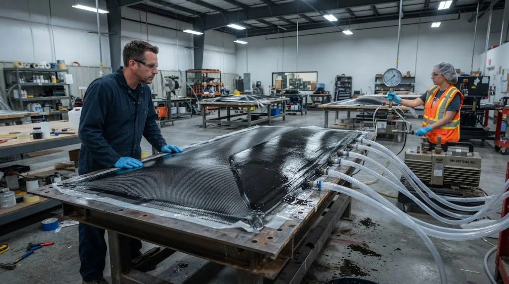
Vacuum infusion has become the default manufacturing process for large composite structures such as wind turbine blades, boat hulls, and rail body shells. The process is attractive because it uses dry reinforcement and light tooling instead of a costly autoclave cycle, yet its economics
Introduction
Vacuum infusion has become the default manufacturing process for large composite structures such as wind turbine blades, boat hulls, and rail body shells. The process is attractive because it uses dry reinforcement and light tooling instead of a costly autoclave cycle, yet its economics rest on a single discipline: getting resin to flow through a complex fiber architecture quickly enough to wet it out, but uniformly enough to avoid dry spots. Failures in this discipline appear as scrap parts, rework, and rejected laminates, so understanding resin flow physics is a direct lever on production yield.
Three interconnected phenomena govern resin flow in vacuum infusion: permeability, race-tracking, and the design of the flow media system. Permeability describes how easily a given fabric stack allows resin to move through it, and its anisotropy — the difference between in-plane and through-thickness flow — dictates where resin travels first. Race-tracking is the preferential flow of resin along gaps at edges, stitches, and tooling steps, which can outrun the intended flow front and seal off un-wetted regions. Flow media are engineered distribution layers that add a fast in-plane channel on top of the reinforcement. This article examines each phenomenon in turn and closes with rules that keep all three working together rather than against each other.
Permeability Fundamentals: Anisotropy and Fiber Architecture
Permeability is the proportionality constant in Darcy's law, which relates the flow rate of a fluid through a porous medium to the pressure gradient driving it. In vacuum infusion the driving pressure is the difference between atmospheric pressure at the inlet and the vacuum level at the outlet, typically 0.8 to 1.0 bar under full vacuum. For a given pressure drop, a reinforcement with higher permeability lets resin travel faster and farther, which is why permeability measurement is the first step in designing any infusion.
The critical feature of fabric permeability is its anisotropy. In a unidirectional carbon fiber fabric, resin flows roughly 10 to 100 times more easily along the fiber direction than across it, because continuous filaments present a lower resistance path in that orientation. Through-thickness permeability is typically another order of magnitude lower still, which means resin fills a laminate mostly in-plane, then has to be drawn downward through the layers to wet them out. The table below summarizes representative values for common reinforcement architectures:
| Reinforcement Architecture | In-Plane Permeability | Through-Thickness Permeability | Typical Role in Infusion |
|---|---|---|---|
| Unidirectional carbon fabric | 1 to 9 x 10⁻¹⁰ m² (fiber direction) | 0.5 to 2 x 10⁻¹² m² | Spar caps, boat stringers |
| Biaxial / multiaxial stitched fabric | 1 to 8 x 10⁻¹⁰ m² (in-plane) | 1 to 4 x 10⁻¹² m² | Blade shells, hull skins |
| 2/2 twill woven fabric | 0.5 to 3 x 10⁻¹⁰ m² | 0.5 to 2 x 10⁻¹² m² | Cosmetic and thin laminates |
| Polyester flow medium | 1 to 10 x 10⁻⁶ m² | 1 to 8 x 10⁻⁷ m² | Surface distribution layer |
Three practical consequences follow from these numbers. First, the flow medium is 10,000 times more permeable than the reinforcement, so resin races across the surface of the part within seconds while the laminate behind the flow front fills slowly. Second, because through-thickness permeability is low, a thick laminate requires more time for full wet-out than the visible surface flow front suggests. Third, permeability is not a fixed material property: compaction pressure, layer nesting, and stitching all change it, so values measured on a loose stack are optimistic compared with a vacuum-bagged, consolidated laminate. These effects make permeability measurement on the actual production stack, not a datasheet, the reliable basis for fill-time estimates.
Race-Tracking: The Leading Cause of Dry Spots
Race-tracking is the rapid flow of resin along a path of higher permeability that was not intended as part of the distribution network. The most common sources are gaps between the reinforcement and the mold edge or bag edge, channels along stitching or binder lines, and steps at ply drop-offs. Because these gaps can have permeabilities two to four orders of magnitude above the fabric, resin shoots along them and reaches the vacuum port long before the bulk of the laminate is wetted. When the leading edge closes the vent, trapped air in the unwetted region can no longer escape, and the part cures with a dry spot exactly where the engineer least wants one.
Preventing race-tracking starts with geometry control. Reinforcement should be cut to fit the cavity within a few millimeters, and edge gaps wider than about 2 mm should be treated as intentional flow channels rather than accidents. Where a gap is unavoidable — a complex curvature, a ply step, a radius — the designer has two choices: block the channel with a sealant or additional fiber to force resin through the laminate, or accept it and place the injection line so that the race-track path fills the region in a controlled manner. The more subtle lesson is that race-tracking is not binary good or bad: a deliberately created edge channel can act as a feeder, while an accidental one produces voids. The difference is whether the designer knows it exists and has accounted for it in the flow plan.
Flow Media Design and Injection Strategy
Flow media turn the permeability of the whole system on its head. A single layer of knit mesh placed between the vacuum bag and the reinforcement creates a distribution plane that spreads resin across the full surface before it soaks downward, which is why almost all production infusions use some form of flow medium or grooved plastic distribution layer. The main selection question is permeability balance: too low a medium permeability and the part infuses slowly; too high and the surface wets out while deep regions lag behind, hiding dry spots until demolding. For thick parts, multiple flow regions, staggered flow media, or a medium applied only over the slow region can reshape the flow front.
Injection strategy is the second lever. Line injection along an edge gives a short flow distance and is the standard for boat hulls and flat panels, while point or spiral injection suits parts with complex geometry. Vacuum level sets the overall driving pressure: most resins infuse well at 0.9 bar of differential, and increasing vacuum beyond the resin's vapor pressure risks boiling volatiles rather than accelerating flow. Resin viscosity, gel time, and the fill-and-wait sequence are the final pieces — the goal is to fill the mold completely, then hold vacuum long enough for the slowest through-thickness path to consolidate before gelation.
- Characterize the real stack: measure permeability, compaction, and nesting on the production layup, not the datasheet.
- Control edge gaps: trim to fit within millimeters; treat gaps wider than 2 mm as designed channels, not accidents.
- Balance flow media permeability against part thickness and resin gel time.
- Use controlled race-tracking: where channels are unavoidable, turn them into feeders and design the injection line around them.
- Observe the flow front: during first infusions, watch front advancement and adjust port placement before committing to production.
- Verify with fill trials: run one sacrificial panel per new part geometry and section it to confirm zero dry spots.
Frequently Asked Questions
Why do dry spots appear even though resin covers the whole surface?
Because surface coverage happens through the flow medium, which is far more permeable than the reinforcement. The visible flow front can reach the vents while below the surface, thicker regions are still unwetted. Dry spots form when a race-tracking channel closes the vacuum vent before the through-thickness flow completes, trapping air in the laminate.
How does permeability anisotropy affect infusion fill time?
Fill time is governed mostly by in-plane flow along the high-permeability direction and by through-thickness flow that takes orders of magnitude longer. A quick surface flow does not mean the laminate is wet. Accurate fill-time prediction requires through-thickness permeability measured under vacuum-bag compaction, because loose measurement stacks dramatically overestimate it.
Can race-tracking ever be beneficial in vacuum infusion?
Yes. A deliberately created edge channel can act as a resin feeder that supplies a complex or slow region from the side. The key is intent and control: a designed channel is placed where it helps the flow plan and its effect is verified, whereas an accidental gap produces voids. The same physical mechanism gives opposite outcomes depending on whether the designer accounts for it.
What is the best injection strategy for a large flat panel?
Line injection along one edge is the standard choice for flat and gently curved panels because it minimizes flow distance and produces a predictable, straight flow front. Point or spiral injection is better suited to complex three-dimensional geometry where a line feed would create long, uncertain flow paths.
Conclusion
Resin flow physics decides the yield of every vacuum infusion line. Permeability anisotropy tells the engineer where resin wants to go; race-tracking shows where it will go unbidden; and flow media plus injection strategy provide the means to steer it. A part infuses successfully when all three are designed as one system: the fabric stack characterized at production compaction, the edge gaps either eliminated or converted into controlled feeders, and the distribution layer matched to part thickness and resin chemistry. Companies that invest in these details convert infusion from a trial-and-error art into a repeatable process.
YongXian supplies carbon fiber fabrics, including unidirectional, biaxial, and woven reinforcements suited to vacuum infusion of blades, hulls, and industrial parts. Explore our carbon fiber reinforcement range or contact our team for fabric architecture and permeability support on your next infusion project.
Part of topic
Related Articles
- Bio-Based Carbon Fiber Precursors: Lignin and Polyethylene for Low-Cost Production
- Large-Tow Carbon Fiber Cost Analysis: 48K vs 60K Price-Performance Comparison
- Carbon Fiber-Resin Interface Bonding: Surface Treatment and Coupling Agent Optimization
- Digital Twin for Carbon Fiber Manufacturing: Real-Time Process Monitoring and Defect Prevention
- Thermoplastic Carbon Fiber Welding for Automotive: Ultrasonic and Induction Welding Process Windows
- Large-Tow Carbon Fiber Wet Spinning: Process Optimization for 48K/60K Production Efficiency
Interested in Custom Carbon Fiber Products?
Contact our team for competitive pricing and technical specifications.
Get a QuoteRelated Products
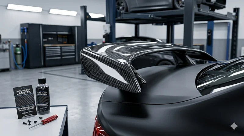
Carbon Fiber Automotive Spoiler
Automotive-grade carbon fiber spoiler manufactured using autoclave-cured pre-preg technology. Each spoiler is vacuum-bagged and oven-cured for optimal fiber-to-resin ratio, strength, and a flawless cosmetic finish.
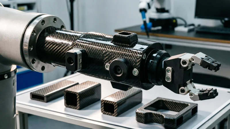
Carbon Fiber Robot End Effector Link — Custom Shape & Sensor Integration
Custom-shaped carbon fiber end effector links for robotic arms. Designed for automation integrators and research labs requiring lightweight, rigid connections between the robot wrist and gripper/tool. Can incorporate sensor mounting bosses, cable routing channels, and quick-change interfaces.

Custom Carbon Fiber Medical Device Components
Medical-grade carbon fiber components manufactured for imaging equipment, surgical instruments, and patient support systems. Carbon fiber's radiolucency (X-ray transparency) and high strength-to-weight ratio make it ideal for CT scanner beds, wheelchair frames, surgical robot arms, and MRI-compatible accessories. Biocompatible resin systems available.

Custom Carbon Fiber Musical Instrument Parts
Carbon fiber components for musical instrument manufacturing offering superior dimensional stability, low weight, and consistent acoustic properties. We produce carbon fiber bows, guitar necks, violin chin rests, drum shells, and wind instrument bodies. Carbon fiber instruments are immune to humidity changes and temperature fluctuations that affect wooden instruments.
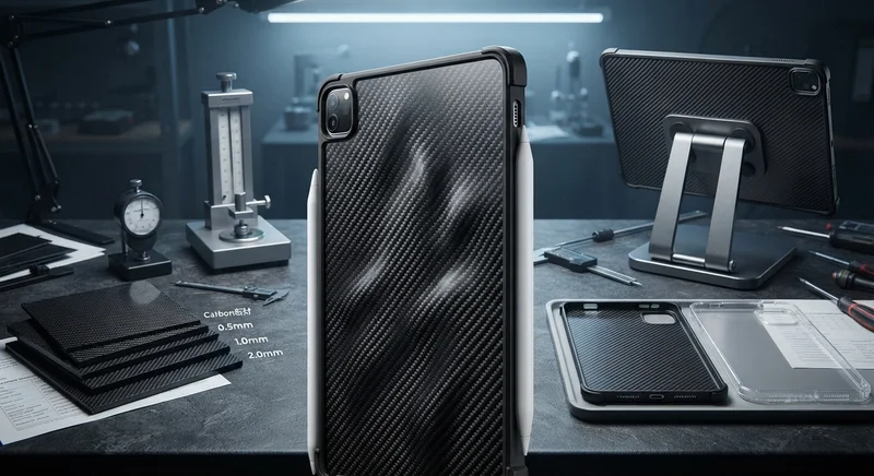
Carbon Fiber Tablet Case — Ultra-Light Protective Shell
Lightweight carbon fiber protective case for tablets and iPads. Molded from T700 3K prepreg with reinforced corner protection. Adds minimal weight while providing superior rigidity and drop protection compared to polycarbonate or silicone cases. Ideal for field workers, enterprise deployments, and professionals requiring durable tablet protection.