
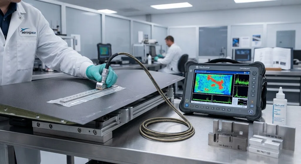
Ultrasonic phased array testing provides high-resolution imaging of internal defects in carbon fiber composites — delaminations, porosity, fiber waviness, and impact damage. This article covers phased array principles, probe selection, and calibration for CFRP inspection.
Introduction
Ultrasonic phased array (PA) testing has become the standard non-destructive inspection method for carbon fiber reinforced polymer (CFRP) structures in aerospace, automotive, and industrial applications. Unlike conventional single-element ultrasonic testing, phased array systems use multi-element probes with electronic beam steering and focusing, providing superior defect detection, characterization, and imaging capabilities.
The growing use of CFRP in safety-critical structures — aircraft primary structures, pressure vessels, wind turbine blades — demands reliable, repeatable NDT methods that can detect and characterize defects before they compromise structural integrity. Phased array technology meets these requirements through its ability to generate cross-sectional images (B-scans), top-down views (C-scans), and through-thickness maps of internal defects.
Phased Array Principles
A phased array probe contains multiple small piezoelectric elements (typically 16–128) arranged in a linear or matrix pattern. By applying precise time delays to each element's excitation pulse, the ultrasonic beam can be steered and focused without physically moving the probe:
Beam steering: Electronic time delays cause the wavefront from each element to arrive at the target location at different times, creating a steered beam that can sweep through angles of 0–70° without probe movement.
Beam focusing: Time delays can focus the beam at specific depths within the CFRP laminate, optimizing resolution at the depth of interest while maintaining coverage of the full thickness.
Multi-angle inspection: A single scan can acquire data from multiple angles simultaneously, providing comprehensive defect detection regardless of defect orientation.
CFRP Inspection Challenges
Carbon fiber composites present unique challenges for ultrasonic inspection:
Attenuation: CFRP attenuates ultrasound more than metals — typically 2–6 dB/mm at 5 MHz — due to scattering at fiber-matrix interfaces and absorption in the viscoelastic matrix. Higher frequencies provide better resolution but suffer greater attenuation.
Velocity variation: Ultrasonic velocity varies with fiber orientation — faster along fibers (3,000–3,500 m/s) than across fibers (2,000–2,500 m/s). This causes beam distortion and requires velocity compensation in phased array algorithms.
Multiple reflections: Thin-ply laminates produce multiple backwall reflections that can mask internal defects. Signal processing techniques — gates, time-of-flight diffraction (TOFD), and synthetic aperture focusing — are used to separate defect signals from structural echoes.
Probe Selection
Phased array probe selection for CFRP inspection depends on the application:
Linear array (1D): Most common for CFRP inspection. 16–64 elements at 0.5–1.0 mm pitch. Provides electronic scanning in one direction with mechanical scanning in the perpendicular direction. Frequency range: 2–10 MHz.
Matrix array (2D): 64–256 elements in a rectangular grid. Enables electronic scanning in both directions, reducing mechanical scanning requirements. Preferred for complex geometry inspection.
Dual-element probes: Separate transmit and receive elements reduce near-surface dead zone, improving detection of near-surface defects. Used for thin laminates (less than 2 mm).
Calibration and Quality
Phased array systems require calibration using reference standards that simulate CFRP defects:
Reference blocks: CFRP blocks with manufactured defects — flat-bottom holes, side-drilled holes, and delaminations — at known depths and sizes. Calibration verifies detection sensitivity and sizing accuracy.
Beam correction: Phased array algorithms must account for CFRP's anisotropic velocity, attenuation, and mode conversion. Beam correction factors are determined during calibration and applied to all inspection data.
Performance verification: Regular verification using calibration blocks ensures consistent detection sensitivity throughout the inspection program.
Applications
Phased array inspection is used across CFRP applications:
Aerospace: Inspection of aircraft composite structures — wing skins, fuselage sections, control surfaces — for manufacturing defects (porosity, delamination) and service damage (impact, fatigue).
Wind energy: Blade inspection for delamination, bond line defects, and fiber waviness in thick-section composite structures.
Automotive: High-speed production inspection of CFRP body panels and structural components, requiring inspection rates of 0.5–2.0 m²/minute.
Conclusion
Ultrasonic phased array testing provides the resolution, sensitivity, and imaging capabilities required for reliable inspection of carbon fiber composite structures. As CFRP use grows in safety-critical applications, phased array technology will continue to advance — with higher element counts, faster processing, and improved algorithms for complex composite geometries.
Part of topic
Related Articles
- Bio-Based Carbon Fiber Precursors: Lignin and Polyethylene for Low-Cost Production
- Large-Tow Carbon Fiber Cost Analysis: 48K vs 60K Price-Performance Comparison
- Carbon Fiber-Resin Interface Bonding: Surface Treatment and Coupling Agent Optimization
- Digital Twin for Carbon Fiber Manufacturing: Real-Time Process Monitoring and Defect Prevention
- Thermoplastic Carbon Fiber Welding for Automotive: Ultrasonic and Induction Welding Process Windows
- Large-Tow Carbon Fiber Wet Spinning: Process Optimization for 48K/60K Production Efficiency
Interested in Custom Carbon Fiber Products?
Contact our team for competitive pricing and technical specifications.
Get a QuoteRelated Products

Carbon Fiber Fishing Rod Blank
High-quality carbon fiber fishing rod blank manufactured from multiple grades of Toray carbon fiber cloth. Available in a wide range of lengths, powers, and actions for freshwater and saltwater applications. Suitable for OEM rod building.
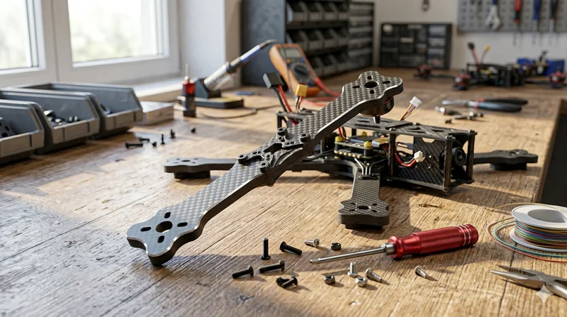
Carbon Fiber Drone Arm
Precision-molded carbon fiber drone arm combining unidirectional fiber for stiffness and woven layers for torsional strength. Designed for FPV, photography, and industrial drone platforms. Each arm is CNC-machined to exact specifications.
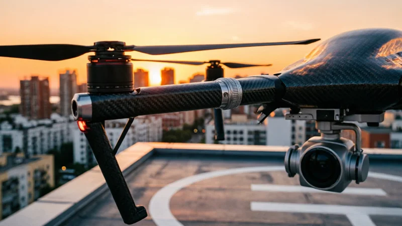
Custom Carbon Fiber Drone Arm — Lightweight & Vibration-Damping
High-modulus carbon fiber drone arms designed for industrial, agricultural, and surveying UAVs. Replace heavy aluminum arms with our custom-molded CFRP arms — 40-60% lighter with superior vibration damping for stable flight and sharper imaging.