
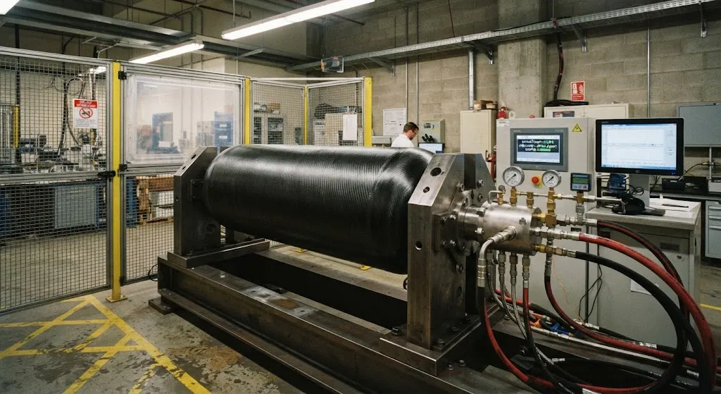
A hydrogen fuel cell vehicle must carry 350 to 700 bar of compressed gas inside a vessel that survives the full service life of the vehicle without a single structural failure, while remaining as light as possible. That combination — extreme pressure, extreme safety consequence, and ext
Introduction
A hydrogen fuel cell vehicle must carry 350 to 700 bar of compressed gas inside a vessel that survives the full service life of the vehicle without a single structural failure, while remaining as light as possible. That combination — extreme pressure, extreme safety consequence, and extreme weight sensitivity — makes the pressure vessel the most tightly regulated component in the entire powertrain. The Type IV design, in which a thin polymer liner provides the gas seal and a filament-wound carbon fiber composite carries all structural load, has become the reference architecture for automotive and heavy-duty hydrogen storage because it delivers the highest gravimetric efficiency: roughly 5.5–6.5 wt% system-level hydrogen storage, compared with 3.5–4.5% for the Type III design with its aluminum liner.
The price of that efficiency is fatigue complexity. Because the composite overwrap, not the liner, carries the pressure load, every refueling event and every thermal cycle becomes a mechanical fatigue event in a laminated structure. Qualification therefore depends on pressure-cycle testing at a scale that dwarfs the compressed natural gas (CNG) experience: hundreds of thousands of cycles, followed by burst, permeation, and residual-strength verification. Understanding how that requirement evolved, and what a 300,000-cycle validation actually proves, is essential for anyone specifying, manufacturing, or certifying Type IV storage.
Type IV Construction and the Fatigue Load Path
A Type IV vessel consists of three functional layers. The inner liner is a blow-molded thermoplastic — typically high-density polyethylene (HDPE) or polyamide (PA6/PA12) — whose only job is to seal the gas. It carries essentially no structural load. The structural layer is a filament-wound carbon fiber composite, usually an epoxy matrix wound in helical and hoop patterns, which resists the internal pressure. An outer protective layer guards against abrasion and ultraviolet exposure.
This load path is what distinguishes Type IV fatigue from metallic vessel fatigue. In a steel or aluminum vessel, fatigue cracks initiate in the metal and grow until leak-before-burst or rupture. In a Type IV vessel, the composite overwrap accumulates matrix microcracks and fiber-matrix debonding over thousands of cycles, while the polymer liner slowly develops its own fatigue response. The liner is designed to leak before the composite bursts, which is why permeation testing is coupled to cycle testing — a liner that cracks is a warning, not a failure, provided the composite retains its burst margin.
Fatigue Mechanisms in CFRP Overwraps
Carbon fiber composites do not exhibit a conventional fatigue endurance limit the way steel does; their fatigue life depends on stress ratio, cycle count, and load path. Under the pressure-cycling regime of a hydrogen tank, three damage mechanisms dominate:
- Matrix microcracking: Transverse cracks develop in the off-axis plies early in life, typically within the first 10,000 cycles. These cracks are generally benign on their own but create pathways for gas permeation and stress concentration.
- Fiber-matrix debonding and delamination: Cyclic shear stresses at ply interfaces promote delamination, which reduces the effective load-bearing cross-section and shifts stress into adjacent plies.
- Fiber fatigue and stress rupture: Under sustained high stress, individual carbon filaments can experience stress-rupture, particularly where manufacturing defects or handling damage have created stress concentrations.
The practical consequence is that Type IV fatigue life is not infinite, and the certification cycle count is set by the demonstrated damage tolerance of the overwrap rather than by a theoretical endurance limit.
Test Methodology and the ISO 11439 Lineage
ISO 11439 established the pressure-cycle framework originally for CNG vehicle cylinders, and the hydrogen industry inherited its methodology: cyclic pressurization between defined pressure limits at controlled rates, with periodic inspection and final burst verification. Hydrogen-specific standards — notably ISO 19881 for land vehicle fuel containers, SAE J2579, and UN Global Technical Regulation No. 13 — adapted that framework to the higher pressures and different failure consequences of hydrogen service.
A modern validation program for a Type IV hydrogen tank typically includes:
| Test | Purpose | Typical requirement |
|---|---|---|
| Pressure cycling | Demonstrate fatigue life of overwrap and liner | Up to 300,000 cycles for Type IV |
| Permeation measurement | Confirm liner integrity throughout life | Below defined leak threshold |
| Burst test after cycling | Confirm residual strength margin | Burst pressure above required minimum |
| Drop and impact | Survivability of handling and crash events | Per vehicle-level requirement |
| Bonfire and gunfire | Extreme event tolerance | No fragmentation per standard |
The evolution toward 300,000-cycle targets reflects both the longer service life expected of commercial heavy-duty vehicles and the conservative approach demanded by hydrogen's wide flammability range and low ignition energy.
Type III vs Type IV: Cycle Requirements and Trade-offs
The Type III vessel uses a thin aluminum liner with a carbon fiber overwrap. Its metal liner is more robust against permeation and handles the load path differently, which historically supported a lower cycle-count requirement — on the order of 150,000 cycles. Type IV, with its thermoplastic liner and lighter construction, is validated to the higher 300,000-cycle regime to compensate for the liner's lower structural contribution and to demonstrate that the all-composite load path can endure a longer service life.
The trade-off is not purely about cycles. Type III offers better permeation resistance and simpler manufacturing, but its aluminum liner adds weight and is susceptible to hydrogen embrittlement at the liner-composite interface. Type IV offers higher gravimetric efficiency and lower cost at scale, but demands more rigorous fatigue and permeation validation. The 300,000-cycle requirement is the mechanism by which regulators ensure that the weight advantage of Type IV does not come at the cost of service-life integrity.
Acceptance Criteria and Failure Modes
A tank passes fatigue qualification only if it satisfies all of the following after cycling: no leakage exceeding the defined permeation threshold, no visible structural damage that compromises the overwrap, and a post-cycle burst pressure above the required minimum. Leak-before-burst behavior — the liner failing before the composite — is the desired outcome, because a slow leak is detectable and non-catastrophic, whereas an overwrap burst is not.
The most common failure modes in validation are liner cracking, which drives permeation above threshold, and delamination in the dome region where the winding pattern transitions from helical to hoop. Both are addressed through winding-pattern optimization, liner material selection, and process control during filament winding.
Frequently Asked Questions
Why do Type IV hydrogen tanks require 300,000 cycles when Type III requires about 150,000?
The higher cycle count compensates for the thermoplastic liner's limited structural contribution and demonstrates that the all-composite load path can sustain a longer service life. Type III's aluminum liner shares more of the load and provides inherent permeation resistance, which supports a lower fatigue requirement. Regulators set the Type IV target conservatively because the composite overwrap is the sole structural element.
What does a pressure-cycle test actually validate?
It validates the fatigue life of the composite overwrap and the integrity of the liner over the intended service life. A complete validation couples cycling with permeation measurement and a post-cycle burst test, so the result proves not only that the tank survives the cycles but that it retains a sufficient burst margin and remains leak-tight afterward.
How does the ISO 11439 framework relate to hydrogen standards?
ISO 11439 established the pressure-cycling methodology for CNG vehicle cylinders. Hydrogen-specific standards such as ISO 19881, SAE J2579, and UN GTR No. 13 adopted and adapted that methodology for higher pressures and different failure consequences. The ongoing revision of these standards is expected to formalize the higher cycle counts now used for Type IV vessels.
Conclusion
Fatigue qualification is the decisive engineering gate for Type IV hydrogen storage. The evolution from the CNG-era ISO 11439 framework to hydrogen-specific regimes has raised the bar to 300,000 pressure cycles, a requirement that reflects both the extended service life of heavy-duty vehicles and the conservative posture demanded by hydrogen safety. For tank manufacturers, meeting that bar depends on winding-pattern optimization, liner material selection, and rigorous process control; for fleet operators, it is the evidence that the lightweight Type IV vessel will remain leak-tight and structurally sound for the life of the vehicle.
For buyers evaluating carbon fiber hydrogen storage solutions, the critical questions are the demonstrated cycle count, the permeation and burst data supporting it, and the manufacturing controls behind the overwrap. Explore our carbon fiber products for hydrogen pressure vessel applications, or contact our engineering team to discuss overwrap design and material selection for your storage program.
Part of topic
Related Articles
- Bio-Based Carbon Fiber Precursors: Lignin and Polyethylene for Low-Cost Production
- Large-Tow Carbon Fiber Cost Analysis: 48K vs 60K Price-Performance Comparison
- Carbon Fiber-Resin Interface Bonding: Surface Treatment and Coupling Agent Optimization
- Digital Twin for Carbon Fiber Manufacturing: Real-Time Process Monitoring and Defect Prevention
- Thermoplastic Carbon Fiber Welding for Automotive: Ultrasonic and Induction Welding Process Windows
- Large-Tow Carbon Fiber Wet Spinning: Process Optimization for 48K/60K Production Efficiency
Interested in Custom Carbon Fiber Products?
Contact our team for competitive pricing and technical specifications.
Get a QuoteRelated Products
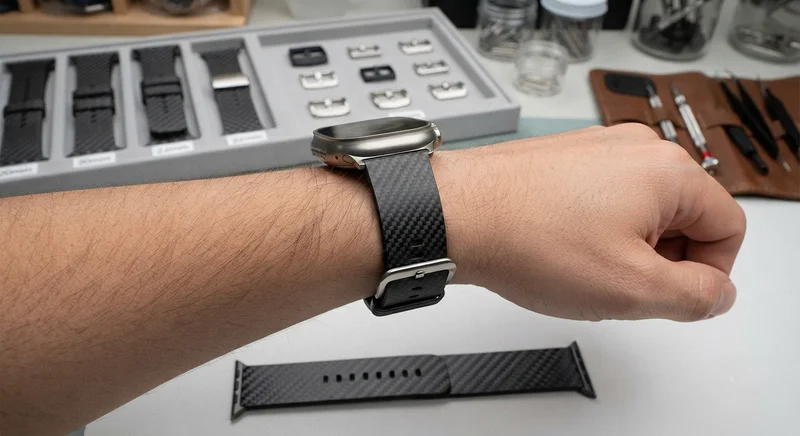
Carbon Fiber Watch Strap — 20mm/22mm Quick-Release
Premium carbon fiber watch strap with quick-release spring bars. Woven from T700 3K twill prepreg with a flexible resin system that conforms to the wrist. Available in 20mm and 22mm lug widths, compatible with Apple Watch, Samsung Galaxy Watch, Garmin, and traditional mechanical watches. Features a stainless steel buckle and carbon fiber keepers. The natural weave pattern makes each strap unique.
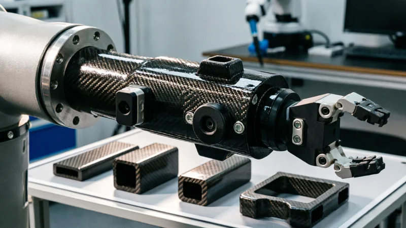
Carbon Fiber Robot End Effector Link — Custom Shape & Sensor Integration
Custom-shaped carbon fiber end effector links for robotic arms. Designed for automation integrators and research labs requiring lightweight, rigid connections between the robot wrist and gripper/tool. Can incorporate sensor mounting bosses, cable routing channels, and quick-change interfaces.

Custom Carbon Fiber Musical Instrument Parts
Carbon fiber components for musical instrument manufacturing offering superior dimensional stability, low weight, and consistent acoustic properties. We produce carbon fiber bows, guitar necks, violin chin rests, drum shells, and wind instrument bodies. Carbon fiber instruments are immune to humidity changes and temperature fluctuations that affect wooden instruments.

Custom Carbon Fiber Medical Device Components
Medical-grade carbon fiber components manufactured for imaging equipment, surgical instruments, and patient support systems. Carbon fiber's radiolucency (X-ray transparency) and high strength-to-weight ratio make it ideal for CT scanner beds, wheelchair frames, surgical robot arms, and MRI-compatible accessories. Biocompatible resin systems available.
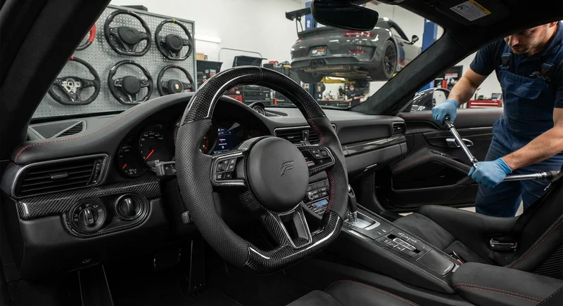
Carbon Fiber Steering Wheel — Custom Leather-Wrapped with CF Inlay
Custom carbon fiber steering wheel with genuine leather wrapping and carbon fiber inlay sections. Molded from T700 3K prepreg for maximum rigidity with a 30% weight reduction over OEM wheels. Available in D-shape (flat bottom) and round profiles. Direct bolt-on fitment for popular sports car and performance vehicle models. Custom stitching color and leather grade available.