

Tow spreading converts standard 12K or 24K carbon fiber tow into wide, thin bands of 25–50 mm width, enabling thin-ply prepreg with areal weights of 40–60 g/m². This article examines pneumatic, mechanical, and vibratory spreading methods, their process windows, and the quality trade-offs in spread tow production.
Introduction
Carbon fiber tow spreading is a critical intermediate process in the production of thin-ply prepreg and spread-tow fabrics. Standard carbon fiber tows — typically 12K (12,000 filaments) or 24K (24,000 filaments) — arrive from the fiber manufacturer as compact, rounded bundles with a cross-sectional width of approximately 3–5 mm. For many high-performance applications, this native tow geometry is too narrow and too thick. Tow spreading transforms the compact tow into a wide, thin band — typically 25–50 mm in width — enabling the production of prepreg with areal weights as low as 40–60 g/m², compared to the 80–120 g/m² achievable with unspread tows.
The drive toward thinner plies originates from the recognition that laminate thickness is the single most influential variable controlling fatigue life, impact resistance, and through-thickness properties in carbon fiber reinforced polymers (CFRP). Thin-ply laminates — defined as plies with thickness below 100 μm — suppress crack initiation, delay delamination, and enable weight-optimized structures that are 10–20% lighter than equivalent thick-ply designs. Tow spreading is the gateway process that makes thin-ply production economically and technically viable.
The Physics of Tow Spreading
Carbon fiber tows consist of thousands of individual filaments held together by sizing chemistry and inter-filament friction. The natural tendency of the filaments is to remain in a compact, roughly elliptical cross-section. Spreading requires overcoming the inter-filament adhesion and friction forces to redistribute the filaments across a wider area.
The key physical parameters governing spreading behavior include:
Inter-filament friction coefficient: Typical carbon fiber tows have a friction coefficient of 0.2–0.4 between filaments, depending on sizing type and content. Lower friction facilitates spreading but may cause filament migration during downstream processing.
Tow tension: Spreading requires controlled tension — too high and the filaments resist redistribution; too low and the tow loses coherence. Optimal spreading tension is typically 0.5–2.0 cN/tex for standard modulus carbon fiber.
Spreading ratio: Defined as the ratio of spread width to original tow width. Practical spreading ratios range from 2.0× to 4.0×, with diminishing returns above 3.5× due to edge filament loss and width non-uniformity.
Line speed: Industrial spreading operates at 5–30 m/min, depending on the method. Higher speeds reduce per-unit cost but may compromise width uniformity and increase filament breakage.
Pneumatic Spreading Technology
Pneumatic spreading uses controlled airflow to separate and redistribute filaments. The most common configuration employs opposed air nozzles positioned above and below the tow path, generating a high-velocity air curtain that penetrates the tow bundle and pushes filaments outward.
Venturi-type spreaders accelerate air through a converging-diverging channel, creating a low-pressure zone that draws filaments apart. These systems achieve spreading ratios of 2.0–3.0× at line speeds of 10–20 m/min. The air velocity typically ranges from 30–60 m/s, with nozzle gap distances of 5–15 mm.
Opposed-jet spreaders use pairs of air nozzles positioned symmetrically above and below the tow. The impinging jets create a stagnation zone that forces filaments to spread laterally. This configuration achieves better width uniformity (CV < 5%) than venturi systems but requires more precise alignment.
Air knife spreaders use a thin, high-velocity air curtain (60–100 m/s) that sweeps across the tow surface. The shear force at the air-fiber interface drags outer filaments outward while the core remains relatively undisturbed. This method is preferred for delicate fibers where minimizing mechanical contact is important.
Pneumatic systems offer the advantage of non-contact spreading, minimizing fiber damage. Filament breakage rates are typically below 0.3%, compared to 1–3% for mechanical methods. However, pneumatic spreading is sensitive to environmental conditions — humidity and static charge affect filament behavior, and the compressed air supply represents a significant operating cost.
Mechanical Spreading Methods
Mechanical spreading uses physical contact between the tow and spreading elements — rods, rollers, or grooved surfaces — to redistribute filaments. While introducing more fiber damage than pneumatic methods, mechanical spreading offers greater process stability and lower operating costs.
Single-rod spreading is the simplest configuration: the tow passes over a smooth rod at an angle, and the lateral component of the contact force pushes filaments outward. The rod diameter (3–10 mm), contact angle (15–45°), and tow tension determine the spreading ratio. Single-rod systems achieve 2.0–2.5× spreading with filament breakage rates of 1–2%.
Multi-rod spreading uses a series of 3–6 rods with increasing diameter to progressively spread the tow. Each rod contributes a partial spreading step, reducing the stress on any single contact point. This approach achieves spreading ratios of 2.5–3.5× with breakage rates of 0.5–1.5%.
Roller spreading uses a pair of counter-rotating rollers with a slight speed differential to create a spreading force. The roller gap, surface finish, and speed ratio control the spreading behavior. Roller systems are favored for high-speed production (> 20 m/min) where rod-based systems may vibrate or cause filament entanglement.
Vibratory Spreading Technology
Vibratory spreading applies high-frequency mechanical oscillation to a spreading element in contact with the tow. The vibration serves two functions: it reduces the effective inter-filament friction by periodically releasing contact forces, and it provides a dynamic spreading force that supplements the static mechanical contact.
Resonant vibratory spreaders operate at the natural frequency of the spreading rod assembly (200–800 Hz), maximizing the amplitude of oscillation for a given energy input. The rod tip amplitude is typically 0.5–2.0 mm, sufficient to disrupt inter-filament adhesion without causing large-scale filament displacement.
Ultrasonic spreaders operate at 20–40 kHz using piezoelectric transducers. The very high frequency and low amplitude (10–50 μm) provide extremely uniform spreading with minimal fiber damage. However, the equipment cost is significantly higher than resonant systems, and the process window is narrower.
Vibratory spreading achieves the best combination of spreading ratio (2.5–4.0×), width uniformity (CV < 3%), and filament integrity (< 0.5% breakage). The technology is particularly favored for aerospace-grade thin-ply prepreg where consistent areal weight and minimal fiber damage are critical quality requirements.
Process Parameters and Optimization
Successful tow spreading requires careful optimization of multiple interacting parameters:
Tow tension control: Inconsistent tension is the primary cause of width variation. Closed-loop tension control using feedback from load cells or dancer rollers maintains tension within ±2% of the target value.
Sizing compatibility: The spreading method must be compatible with the fiber sizing. Epoxide-based sizings (most common) respond differently to mechanical stress than polyurethane sizings. Some sizings become tacky during spreading, causing filament bundling; others become brittle and increase breakage rates.
Static elimination: Carbon fiber tows develop significant static charge during spreading, particularly in dry environments. Ionizing air bars or anti-static sprays are essential to prevent filament repulsion and width instability.
Temperature and humidity: Optimal spreading occurs at 20–25°C and 45–65% relative humidity. Low humidity increases static; high humidity can cause sizing swelling and increased friction.
Thin-Ply Prepreg Production
The primary application of spread tow is thin-ply prepreg manufacturing. In the prepregging process, the spread tow is impregnated with resin (typically epoxy) and sandwiched between release films. The key advantage of spread tow is the dramatically reduced ply thickness — from 120–150 μm for conventional prepreg to 40–60 μm for spread-tow prepreg.
Thin-ply prepreg offers measurable performance advantages:
Fatigue life: CFRP laminates made from thin-ply prepreg show 2–5× improvement in fatigue life compared to conventional-thickness laminates. The mechanism is suppression of matrix micro-cracking, which is the initiating event for fatigue damage.
Impact resistance: Thin-ply laminates absorb 20–40% more energy before visible damage, due to more uniform stress distribution and delayed delamination onset.
Surface finish: Thin plies conform better to mold surfaces, reducing print-through and improving Class A surface quality for automotive and aerospace applications.
Weight optimization: The combination of thinner plies and more uniform resin distribution enables 10–15% weight reduction in equivalent-stiffness designs.
Industrial Applications and Market Trends
The thin-ply prepreg market is growing at 15–20% annually, driven by aerospace lightweighting demands and increasing adoption in high-performance sporting goods.
Aerospace: Airbus, Boeing, and their Tier-1 suppliers are evaluating thin-ply prepreg for secondary structures, control surfaces, and interior panels. The A350 XWB and 787 Dreamliner programs have identified thin-ply as a weight reduction opportunity for next-generation variants.
Sporting goods: Premium tennis rackets, badminton rackets, cycling frames, and Formula 1 components increasingly use thin-ply carbon prepreg. The performance benefits — improved fatigue life, better surface finish, and weight reduction — justify the higher material cost.
Automotive: Thin-ply prepreg is being evaluated for high-volume automotive structures where weight reduction directly impacts range (EV) or fuel economy. The challenge is reducing prepreg cost from current aerospace levels ($80–150/kg) to automotive targets ($15–30/kg).
Conclusion
Tow spreading is a mature but evolving technology that enables the production of thin-ply carbon fiber prepreg — a material class with measurably superior mechanical properties compared to conventional-thickness prepreg. Pneumatic, mechanical, and vibratory spreading methods each offer distinct trade-offs in spreading ratio, uniformity, fiber damage, and cost. As the demand for thinner, lighter, and more durable CFRP structures grows across aerospace, automotive, and sporting goods applications, tow spreading technology will continue to advance in speed, precision, and economic viability.
Part of topic
Related Articles
- Bio-Based Carbon Fiber Precursors: Lignin and Polyethylene for Low-Cost Production
- Large-Tow Carbon Fiber Cost Analysis: 48K vs 60K Price-Performance Comparison
- Carbon Fiber-Resin Interface Bonding: Surface Treatment and Coupling Agent Optimization
- Digital Twin for Carbon Fiber Manufacturing: Real-Time Process Monitoring and Defect Prevention
- Thermoplastic Carbon Fiber Welding for Automotive: Ultrasonic and Induction Welding Process Windows
- Large-Tow Carbon Fiber Wet Spinning: Process Optimization for 48K/60K Production Efficiency
Interested in Our Products?
Contact our team for competitive pricing and technical specifications.
Get a QuoteRelated Products

Carbon Fiber Fishing Rod Blank
High-quality carbon fiber fishing rod blank manufactured from multiple grades of Toray carbon fiber cloth. Available in a wide range of lengths, powers, and actions for freshwater and saltwater applications. Suitable for OEM rod building.

Carbon Fiber Plate — 3K Twill T700 3.0mm
Medium-thickness 3.0mm carbon fiber plate offering significantly higher load capacity while maintaining attractive 3K twill finish. Suitable for structural brackets, reinforcement plates, and load-bearing panels.

Carbon Fiber Plate — 3K Twill T700 1.5mm
Thin 1.5mm carbon fiber plate with 3K twill weave surface. Lightweight and stiff, commonly used for covers, panels, drone bodies, and applications requiring a premium aesthetic appearance.

Square Carbon Fiber Tube — 3K Twill T700
Square cross-section carbon fiber tube manufactured with 3K twill weave for torsional strength. Preferred for structural frames, trusses, and support columns where rectangular geometry offers design flexibility.
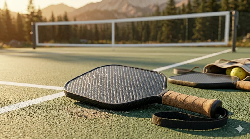
Carbon Fiber Pickleball Paddle
High-performance pickleball paddle with Toray T700 carbon fiber face and polypropylene honeycomb core. Delivers excellent power-to-weight ratio, spin generation, and vibration dampening for competitive play.