
Thermoplastic stamp forming is the process that puts carbon fiber composites on the same production clock as stamped steel. A consolidated thermoplastic laminate is heated above the matrix melt temperature, transferred to a press, and formed between matched metal dies in a cycle that ty
Introduction
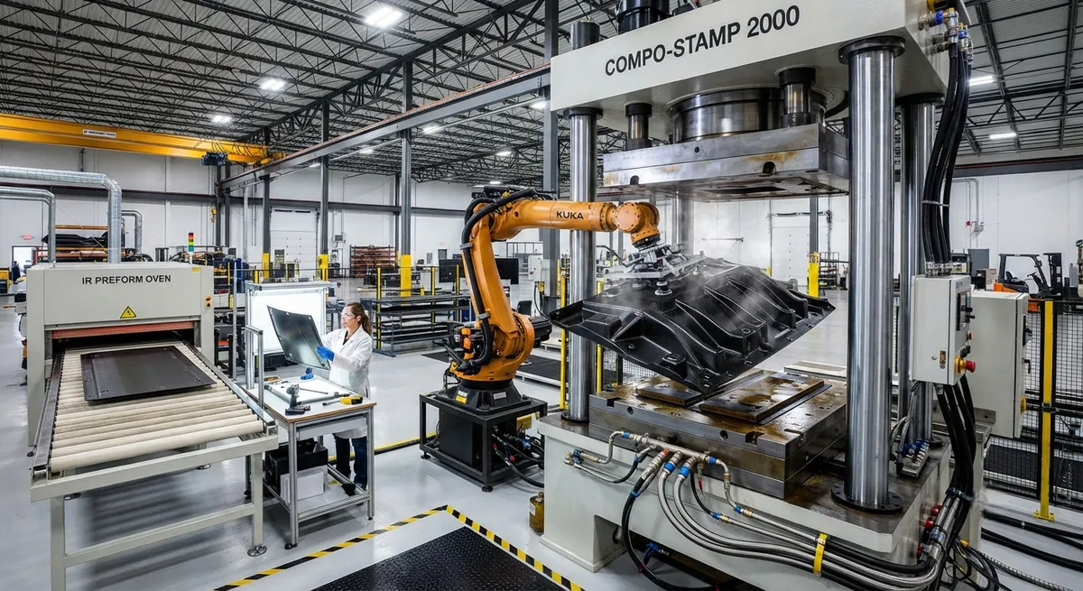
Thermoplastic stamp forming is the process that puts carbon fiber composites on the same production clock as stamped steel. A consolidated thermoplastic laminate is heated above the matrix melt temperature, transferred to a press, and formed between matched metal dies in a cycle that typically runs 30-90 seconds — comparable to the takt time of a body-in-white stamping line. The automotive industry has pursued this process for two decades because it is the only composite manufacturing route whose cycle time scales to vehicle production volumes, and recent programs in structural battery enclosures, seat structures, and crash-relevant floor components have moved it from pilot to production.
The process succeeds or fails on three technical pillars: the cycle time budget, the consolidation quality achieved at high forming pressure, and the tooling design that makes net-shape forming possible without wrinkles or fiber damage. This article examines each pillar with production data, then outlines the material and equipment requirements that a stamp forming program must satisfy.
The Cycle Time Budget: Where the Seconds Go
A stamp forming cycle is not one step but a sequence, and each step consumes time. The table below shows a representative cycle budget for an automotive structural part formed from a carbon fiber/PPS or carbon fiber/PA6 laminate:
| Process Step | Typical Duration | Notes |
|---|---|---|
| Blank heat-up (infrared oven) | 30-90 s | Heated above Tm; automation carries blank to press |
| Transfer to press | 3-8 s | Must stay above Tm; thermal budget is critical |
| Forming stroke | 2-5 s | Matched dies close; laminate drapes and consolidates |
| Consolidation dwell under pressure | 10-30 s | Full pressure held to freeze the part above Tg |
| Die open and part ejection | 5-10 s | Cooled part below Tg in die; automation removes |
| Total cycle | 50-140 s | vs. 15-40 s for unreinforced stamped steel |
The two levers that compress the cycle are heat-up speed and in-die cooling. Infrared ovens with high power density can heat a 1-2 mm laminate from room temperature to 350°C in 30-45 seconds. In-die cooling, where the tool itself is temperature-controlled, freezes the part below the glass transition temperature while it is still under pressure, eliminating a separate cooling station. With both levers optimized, automotive programs report cycles of 60-90 seconds for structural parts — still slower than steel, but no longer a disqualifying gap.
Consolidation Quality at High Pressure
Stamp forming consolidates the laminate during the forming stroke itself, using the press force. Forming pressures of 10-50 bar are typical, far higher than the 1-3 bar of hot drape forming, and this pressure is what closes microscopic voids and promotes interlaminar bonding. The quality outcomes are well documented:
- Void content: At 10-20 bar forming pressure, void content of 1-2% is achievable with a good starting laminate; at 30-50 bar with optimized temperature, values below 1% are reported — comparable to autoclave consolidation.
- Interlaminar shear strength: Stamped laminates typically retain 90-100% of the original consolidated laminate's interlaminar shear strength when the forming temperature window is respected, because the matrix re-melts and re-bonds across the full interface.
- Fiber volume fraction: The starting laminate's fiber volume fraction is preserved during forming; pressure redistributes resin but does not change fiber content.
- Defect risk at features: Sharp radii, ribs, and bosses concentrate both pressure and fiber strain. Without proper radius design (typically ≥3-5 mm for stamping) and blank holder control, these features produce fiber wash or resin starvation.
The practical consequence is that consolidation quality is decided by the starting laminate and the temperature window, not by the press force alone. A well-consolidated, low-void blank formed inside its window will come out of the press consolidated; a marginal blank will not be healed by pressure.
Tooling Design Rules for Net-Shape Stamping
Net-shape stamp forming requires matched metal dies, and the die design determines both part quality and tool life. The governing rules are established across automotive and aerospace stamping programs:
- Thermal control is the tool's primary job: Stamp forming dies run hot (typically 180-220°C for PPS, 200-250°C for PEEK-family matrices) to keep the part above Tg during forming and are then cooled to freeze it. Tool temperature uniformity across the cavity — within ±5°C — is a prerequisite for consistent springback and crystallinity.
- Radius and draft: Minimum inside radii of 3-5 mm and draft angles of 1-3 degrees prevent fiber bridging and ease ejection. Sharper features require local redesign or secondary operations.
- Blank holders and edge restraint: Adjustable blank holders control material flow into the cavity, preventing wrinkles in deep draws and fiber wash at shear-lip features.
- Hardened tool steels with low friction coatings: High forming temperatures and glassy polymer melt demand tool surfaces that resist wear and release the part cleanly; P20 and H13 steels with PVD coatings are common, with tool life reported in the tens of thousands of cycles.
- Venting: Trapped air between the blank and die must escape through micro-venting or engineered gaps; trapped air is the most common cause of surface voids in stamped parts.
Die cost is the capital barrier of stamp forming: a production set for an automotive part typically runs $100,000-500,000 depending on size and complexity. This is why stamp forming is justified only by volume — the amortized tooling cost per part falls below compression molding and autoclave alternatives at volumes in the tens of thousands per year.
Materials and Equipment Requirements
Not every carbon fiber laminate is stampable. The material must deliver two properties simultaneously: high melt flow for forming and high stiffness above Tg for part handling. The practical requirements are:
| Requirement | Why It Matters | Typical Solution |
|---|---|---|
| Low-void consolidated blank | Pressure cannot heal a porous starting laminate | Consolidated OML panels or roll-formed sheet, void content <1% |
| High-melt-flow matrix | Must fill ribs and bosses at 10-50 bar | PA6, PA66, PPS with tailored molecular weight |
| Reinforcement architecture for shear | Fabric or tailored blank drapes over double curvature | Twill or satin weave fabrics; UD tapes for load paths |
| High-rate handling automation | Blank must move from oven to press above Tm | Robotic transfer with thermal budget <8 s |
| Temperature-controlled die system | In-die cooling sets crystallinity and springback | Heated/cooled dies with closed-loop control |
The equipment set — infrared oven, high-speed press with 200-400 ton capacity for automotive parts, temperature-controlled dies, and robotic transfer — represents a capital investment of roughly $1-3 million for a production cell, comparable to a medium-size metal stamping line and well below autoclave infrastructure for the same part value.
Cost Comparison Across Composite Routes
For a representative automotive structural part at three annual volumes, the total manufactured cost per part (including amortized tooling) ranks as follows:
| Volume (parts/year) | Stamp Forming | Compression Molding (thermoset) | Prepreg + Autoclave |
|---|---|---|---|
| 1,000 | $$$ (dies dominate) | $$ | $$ |
| 10,000 | $$ | $$ | $$$ |
| 50,000+ | $ (lowest) | $$ | $$$$ |
At 50,000 parts per year, stamp forming's cycle time advantage — roughly 4-6 times faster than thermoset compression molding with a comparable part — makes it the lowest-cost composite route. The crossover point, where stamp forming becomes cheaper than compression molding, typically occurs between 10,000 and 30,000 parts per year depending on part size and die complexity.
Frequently Asked Questions
How fast is thermoplastic stamp forming compared with compression molding of thermosets?
For an equivalent automotive structural part, stamp forming cycles run 50-140 seconds versus roughly 5-15 minutes for thermoset compression molding (which includes cure time in the heated mold). That is a 4-6 times improvement in cycle time. The gap comes from the thermoplastic's ability to consolidate in seconds once molten and freeze in the cooled die, whereas the thermoset must chemically cure under heat for minutes. At annual volumes above roughly 10,000-30,000 parts, this cycle advantage more than offsets the higher tooling cost of matched metal dies.
What causes defects in stamped thermoplastic carbon fiber parts, and how are they prevented?
The three most common defects are wrinkles (from excess material that cannot shear away), fiber wash (fiber movement at sharp features), and surface or internal voids (from trapped air). Wrinkles are prevented with blank holder control that meters material flow and with reinforcement architectures that shear easily, like twill fabrics. Fiber wash is prevented with generous radii (≥3-5 mm) and controlled blank positioning. Voids are prevented by proper venting of the die cavity and by starting from a low-void consolidated laminate. Each defect class is also caught by in-line monitoring — die temperature and press force curves are recorded per part and compared against qualified process windows.
Is thermoplastic stamp forming limited to automotive, or does it work for aerospace parts?
Stamp forming works for any application where volume justifies matched tooling and where the part geometry suits a press. In aerospace it is used for high-volume structural details — brackets, clips, seat components, and floor structures — rather than large skins, because the press bed size and die cost scale with part area. For large doubly curved panels, hot drape forming or continuous processes remain more economical. The aerospace qualification path is well established: stamped parts are qualified with the same process-control and non-destructive testing framework used for other thermoplastic structures.
Conclusion
Thermoplastic stamp forming compresses carbon fiber composite manufacturing into the cycle-time world of metal stamping. With heat-up, transfer, forming, and in-die cooling optimized, structural parts cycle in 60-90 seconds at forming pressures of 10-50 bar, producing void contents below 1-2% and net-shape geometry directly from the press. The economics cross over from compression molding at volumes of roughly 10,000-30,000 parts per year, making stamp forming the volume route for composites in automotive and high-rate aerospace applications.
For manufacturers evaluating a high-volume composite program, stamp forming deserves analysis whenever cycle time and net-shape output are the deciding factors. Explore our thermoplastic carbon fiber laminates, fabrics, and tapes suitable for stamp forming, or contact our engineering team to discuss material selection and process qualification for your production line.
Part of topic
Related Articles
- Carbon Fiber Drone Blades and Propellers: Stiffness, Balance and Noise Reduction
- Fiberglass Filament Wound Tubes: Cost-Effective Alternative to Carbon Fiber
- Filament Wound Epoxy Tube Design: Wall Thickness, Fiber Angle and Load Optimization
- Filament Wound Epoxy Tubes: Testing Standards and Quality Assurance
- Filament Wound Epoxy Tubes Manufacturing: Process and Quality Control
- Filament Wound Fiberglass Tube: Process Parameters and Performance vs Carbon Fiber
Interested in Our Products?
Contact our team for competitive pricing and technical specifications.
Get a QuoteRelated Products

Carbon fiber standard plate-3k stripe
Lightweight, ultra-rigid standard sheets for drone fuselages, robot housings, facades and structural applications.

Carbon Fiber Plate — 3K Twill T700 3.0mm
Medium-thickness 3.0mm carbon fiber plate offering significantly higher load capacity while maintaining attractive 3K twill finish. Suitable for structural brackets, reinforcement plates, and load-bearing panels.

Carbon Fiber Plate — 3K Twill T700 1.5mm
Thin 1.5mm carbon fiber plate with 3K twill weave surface. Lightweight and stiff, commonly used for covers, panels, drone bodies, and applications requiring a premium aesthetic appearance.

Custom Carbon Fiber Medical Device Components
Medical-grade carbon fiber components manufactured for imaging equipment, surgical instruments, and patient support systems. Carbon fiber's radiolucency (X-ray transparency) and high strength-to-weight ratio make it ideal for CT scanner beds, wheelchair frames, surgical robot arms, and MRI-compatible accessories. Biocompatible resin systems available.

Square Carbon Fiber Tube — 3K Twill T700
Square cross-section carbon fiber tube manufactured with 3K twill weave for torsional strength. Preferred for structural frames, trusses, and support columns where rectangular geometry offers design flexibility.