
In-situ consolidation is the manufacturing route that removes the autoclave from thermoplastic composite production. Instead of laying prepreg plies and then curing the stack for hours under pressure, an automated fiber placement head heats a narrow zone of carbon fiber towpreg, presses
Introduction
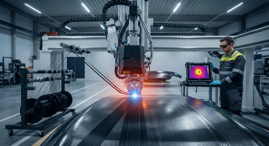
In-situ consolidation is the manufacturing route that removes the autoclave from thermoplastic composite production. Instead of laying prepreg plies and then curing the stack for hours under pressure, an automated fiber placement head heats a narrow zone of carbon fiber towpreg, presses the softened tape against the substrate, and lets it cool and crystallize — all in one continuous pass. The promise is dramatic: autoclave cycle times measured in hours collapse to placement speeds of several meters per minute, and the energy, tooling, and floor space of a pressure vessel disappear from the factory.
The obstacle is quality. A laminate produced in-situ must match autoclave properties, and the single most watched metric is void content — air and volatiles trapped between tows and plies. Production-grade consolidation targets voids below 1%, which demands that the heat source and the compaction parameters work as one system. This article compares the four heat source technologies used in AFP heads, explains where voids come from, and maps the process window that keeps them out.
How In-Situ Consolidation Works
Thermoplastic towpreg — carbon fibers impregnated with a semi-crystalline matrix such as PEEK, PEKK, or PAEK — must be heated above its melt temperature, consolidated under pressure, and cooled at a controlled rate to develop crystallinity. In the AFP process this sequence happens in a window of a few seconds at each position along the path:
- Heating: The tape is raised to 380-430°C for PEEK-family matrices within a narrow zone 20-60 mm wide, without degrading the polymer.
- Compaction: A roller or shoe applies pressure as the tape meets the substrate, squeezing air out of the interface and driving polymer-chain diffusion across the bond line.
- Cooling and crystallization: The consolidated tape quenches as the head moves on; cooling rate determines crystallinity, typically targeted at 30-40% for balanced mechanical and chemical properties.
Placement speeds range from 1 to 10 meters per minute depending on the heat source, the laminate thickness, and the allowable residual stress. The physics repeats thousands of times per part, which is why the heat source and its control loop decide more about laminate quality than any other subsystem.
AFP Heat Source Options
Four heat source families have been engineered onto AFP heads. Each trades maximum heat delivery, control precision, cost, and maturity against the others:
| Heat source | Peak delivery | Typical line speed | Control precision | Capital cost | Production maturity |
|---|---|---|---|---|---|
| Diode laser | 1-4 kW concentrated | 5-15 m/min | Closed loop to ±5-10°C | High | Production |
| Hot gas torch | Moderate, dilute | 1-5 m/min | Coarse | Low | Research |
| Infrared emitters | High, broad area | 2-6 m/min | Medium | Medium | Development |
| Ultrasonic | Mechanical, localized | 2-8 m/min | Medium | Medium | Development |
Diode lasers dominate production AFP because they deliver high power into a small, precisely steered spot with a fast closed-loop thermal camera, enabling the highest placement speeds with repeatable quench conditions. Hot gas torches are inexpensive and simple but their heat is diffuse, limiting speed and making temperature control difficult on curved geometry. Infrared provides broad uniform heating and tolerates varying tow widths, but its large heated zone slows the quench and complicates crystallinity control. Ultrasonic heads convert mechanical vibration into heat directly at the interface, which is efficient for thick stacks but creates a different thermal history that must be qualified case by case.
Void Formation and Control
Voids are the failure signature of in-situ consolidation. Three mechanisms generate them, and each maps to a specific process lever:
- Air entrapment at the tape interface: As the hot tape meets the substrate, air can be trapped between asperities. Higher compaction force and a longer consolidation foot squeeze it out.
- Fiber-bed porosity: Dry spots in the towpreg, from incomplete impregnation or tow gaps, appear as voids after consolidation. Material quality, not process, controls this source.
- Matrix degradation gas: Overheating the polymer creates volatiles that form bubbles. Temperature overshoot of even 30-50°C above the melt window is enough to nucleate them.
The process window below is representative for PEEK-family towpreg in laser AFP; deviations of any one parameter push void content up sharply:
| Parameter | Typical window | Effect when off-target |
|---|---|---|
| Consolidation temperature | 380-430°C | Below: poor bonding; above: degradation bubbles |
| Compaction force per roller | 0.3-1.5 kN | Too low: entrapped air remains |
| Line speed | 1-10 m/min | Faster: less dwell, more voids |
| Heating zone width | 20-60 mm | Wider: slower quench, lower crystallinity |
| Cooling rate | 1-50°C/s | Very fast: amorphous matrix risk |
In practice, achieving and holding a 1% void target requires the temperature and force to be coordinated through process models, because the required heat input rises with speed while the compaction dwell time falls. Production cells run nested control loops: a thermal camera or pyrometer feeds the laser power, while load cells on the roller maintain compaction force, and both are adjusted against a layup plan that varies with curvature and ply count.
Monitoring and Qualification
Because voids form in seconds, offline inspection alone cannot protect a production run. Inline methods are now standard on capable AFP cells: infrared thermal imaging monitors the melt zone shape and temperature distribution; ultrasonic or laser-ultrasonic sensors measure bond quality at the placement point; and machine-vision systems flag tow gaps, wrinkles, and foreign debris. Offline, the finished part is verified with ultrasonic C-scan and, for thick sections, computed tomography, with acceptance criteria typically set at void content below 1% by volume. Mechanical qualification then confirms that interlaminar shear strength and compression-after-impact values match the autoclave baseline — the data that ultimately convinces certification authorities to accept the faster process.
Frequently Asked Questions
Can in-situ consolidation really match autoclave quality?
For well-controlled systems, yes. Production laser-based AFP with tight thermal control routinely reaches void contents below 1%, and reported interlaminar shear strength values reach 85-95% of autoclave-processed laminates of the same material. The qualification path is demanding — every heat source, matrix system, and part geometry must be demonstrated separately — but the gap has closed enough that in-situ consolidation is used in production applications including stiffeners, stringers, and fuselage panels, where its elimination of the autoclave reduces cycle time from hours to minutes and cuts tooling cost. The residual differences appear mainly in crystallinity distribution through thick sections and in the consistency of bonding at complex geometry, which is why part-specific qualification remains mandatory.
Why is a laser preferred over hot gas or infrared for AFP?
Power density and control. A diode laser delivers 1-4 kW into a spot a few centimeters wide, which lets the head run at 5-15 m/min while a fast thermal camera closes the loop on temperature to roughly ±5-10°C. Hot gas torches simply cannot concentrate that much energy, so they are limited to 1-5 m/min and struggle with curved paths. Infrared heats a broad zone, which trades away the rapid quench needed to control crystallinity. Laser hardware is the most expensive option, but the productivity and repeatability gains usually justify it for production; hot gas remains attractive for prototype cells and low-rate research where capital cost dominates.
What causes porosity in thermoplastic AFP and how is it measured?
Three sources dominate: air trapped at the tape-to-substrate interface, pre-existing dry spots from incomplete towpreg impregnation, and volatiles released by matrix overheating. The first is controlled with compaction force and consolidation foot geometry, the second by towpreg quality and storage, and the third by temperature control. Measurement is done inline with ultrasonic or laser-ultrasonic sensors during placement and offline with ultrasonic C-scan or computed tomography on the finished part. Acceptance for structural aerospace parts is typically void content below 1% by volume; at that level, C-scan attenuation and computed-tomography porosity maps provide the documented evidence certification bodies require.
Conclusion
In-situ consolidation of thermoplastic prepreg is the technology that makes thermoplastic composites economically competitive for high-rate production. The laser-based AFP cell, with its closed-loop thermal control and precision compaction, has brought void content below 1% and placement speeds to 5-15 m/min, while hot gas, infrared, and ultrasonic sources serve niches defined by cost and part geometry. The process window — temperature, force, speed, and cooling rate — must be held together as one controlled system, because voids punish any single deviation within seconds.
For manufacturers evaluating in-situ consolidation, the practical checklist is: qualify the heat source against your towpreg's melt window, instrument the cell with inline bond inspection, and require void content evidence on representative geometry before approving a process. Explore our carbon fiber towpreg and thermoplastic prepreg range, or contact our engineering team to discuss heat source selection and process qualification for your AFP program.
Part of topic
Related Articles
- Bio-Based Carbon Fiber Precursors: Lignin and Polyethylene for Low-Cost Production
- Large-Tow Carbon Fiber Cost Analysis: 48K vs 60K Price-Performance Comparison
- Carbon Fiber-Resin Interface Bonding: Surface Treatment and Coupling Agent Optimization
- Digital Twin for Carbon Fiber Manufacturing: Real-Time Process Monitoring and Defect Prevention
- Thermoplastic Carbon Fiber Welding for Automotive: Ultrasonic and Induction Welding Process Windows
- Large-Tow Carbon Fiber Wet Spinning: Process Optimization for 48K/60K Production Efficiency
Interested in Custom Carbon Fiber Products?
Contact our team for competitive pricing and technical specifications.
Get a QuoteRelated Products

Carbon Fiber Fishing Rod Blank
High-quality carbon fiber fishing rod blank manufactured from multiple grades of Toray carbon fiber cloth. Available in a wide range of lengths, powers, and actions for freshwater and saltwater applications. Suitable for OEM rod building.
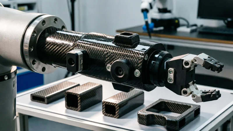
Carbon Fiber Robot End Effector Link — Custom Shape & Sensor Integration
Custom-shaped carbon fiber end effector links for robotic arms. Designed for automation integrators and research labs requiring lightweight, rigid connections between the robot wrist and gripper/tool. Can incorporate sensor mounting bosses, cable routing channels, and quick-change interfaces.

Custom Carbon Fiber Medical Device Components
Medical-grade carbon fiber components manufactured for imaging equipment, surgical instruments, and patient support systems. Carbon fiber's radiolucency (X-ray transparency) and high strength-to-weight ratio make it ideal for CT scanner beds, wheelchair frames, surgical robot arms, and MRI-compatible accessories. Biocompatible resin systems available.

Custom Carbon Fiber Musical Instrument Parts
Carbon fiber components for musical instrument manufacturing offering superior dimensional stability, low weight, and consistent acoustic properties. We produce carbon fiber bows, guitar necks, violin chin rests, drum shells, and wind instrument bodies. Carbon fiber instruments are immune to humidity changes and temperature fluctuations that affect wooden instruments.
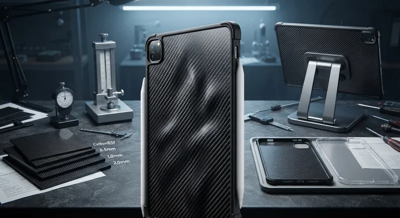
Carbon Fiber Tablet Case — Ultra-Light Protective Shell
Lightweight carbon fiber protective case for tablets and iPads. Molded from T700 3K prepreg with reinforced corner protection. Adds minimal weight while providing superior rigidity and drop protection compared to polycarbonate or silicone cases. Ideal for field workers, enterprise deployments, and professionals requiring durable tablet protection.