
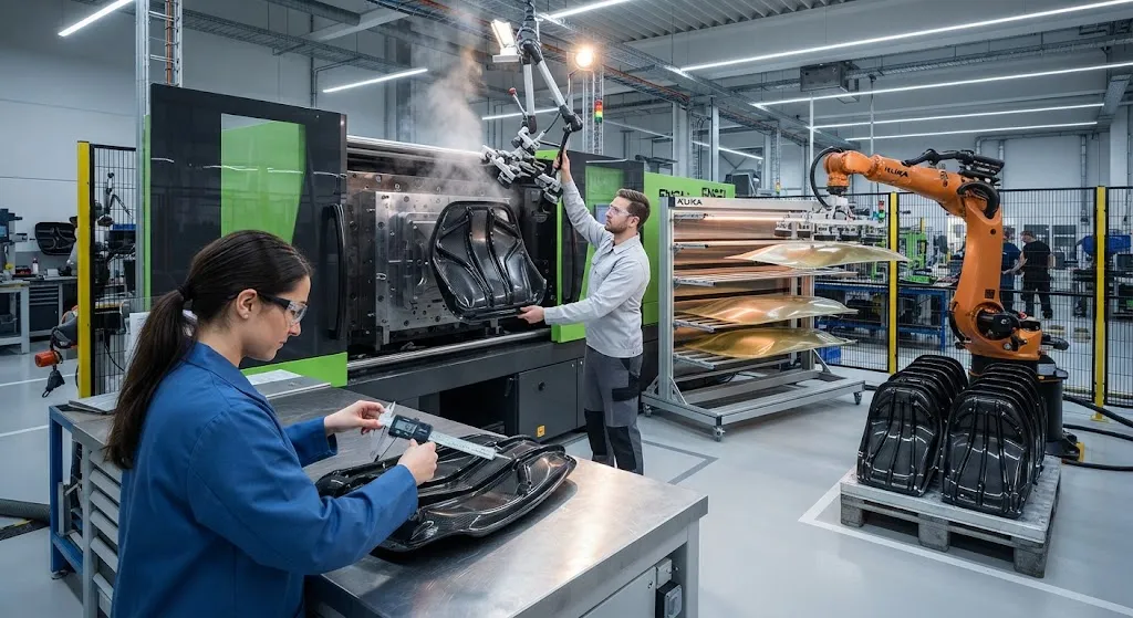
Thermoplastic overmolding is the manufacturing route that turns carbon fiber from a material problem into a production advantage. Instead of molding a structural part and then fastening or bonding brackets, ribs, flanges, and housings onto it, the entire assembly is made in one mold cyc
Introduction
Thermoplastic overmolding is the manufacturing route that turns carbon fiber from a material problem into a production advantage. Instead of molding a structural part and then fastening or bonding brackets, ribs, flanges, and housings onto it, the entire assembly is made in one mold cycle: a continuous-fiber organosheet or laminate is placed in the cavity as an insert, and an injection molding machine shoots short-fiber thermoplastic around it. Ribs, bosses, clips, and attachment points are formed by the injection step, while the continuous fibers carry the structural load. The result is a part with the stiffness of a composite laminate and the part count of a single molding — in cycles measured in tens of seconds to a few minutes.
The two questions that decide whether overmolding works for a given application are cycle time and bond quality. The cycle time must beat the alternative of molding and assembling several components; the bond between the overmolded ribs and the continuous-fiber insert must survive the loads that the part will see in service. Both are controlled by materials selection, tool design, and process parameters that this article examines in turn.
How Thermoplastic Overmolding Works
The process begins with a preform: a flat organosheet — a woven or unidirectional laminate of continuous carbon fiber in a thermoplastic matrix such as PA6, PA66, or PEEK — that is cut to blank size and often preheated in an infrared oven to soften the matrix. The hot blank is transferred to the injection mold, which is held at a tool temperature appropriate for the matrix. The mold closes, and the injection unit shoots a short-fiber-reinforced thermoplastic (typically 20-40 percent glass or carbon fiber in the same polymer family as the insert) into the cavities around and over the insert.
The injection step does two jobs at once. It forms the ribs, bosses, and attachment geometry, and it simultaneously welds itself to the insert: the molten polymer arrives hot enough to melt the surface layer of the insert matrix, and the two then cool and crystallize together, forming a continuous polymer structure across the interface. Because the insert matrix and the injected polymer are the same chemical family, the interface can reach the strength of the bulk material rather than the strength of an adhesive joint.
Material Systems and Architecture
Three main architectures cover most overmolded parts, and the table below compares them:
| Architecture | Continuous-Fiber Insert | Injected Structure | Typical Fiber Content | Best Fit |
|---|---|---|---|---|
| Organosheet + short fiber | Woven or UD laminate | Short-fiber ribs and bosses | Insert 45-60%, overmold 20-40% | Structural panels with ribs |
| Short-fiber only | None | Short-fiber whole part | 20-40% | Low-cost housings and covers |
| Hybrid (UD tape inserts) | Localized UD strips | Short-fiber body | Localized up to 60% | High-load paths in complex parts |
The organizer principle is to put continuous fibers where the load is concentrated and use short fibers where geometry dominates. A seatback, for example, gets a full organosheet base and thin overmolded ribs that need no steel inserts or fasteners; an aerospace bracket gets localized unidirectional tape in the load path and short-fiber flanges around it. The matrix choice is driven by service temperature and chemical resistance: polyamide for structural automotive parts, PP for cost-sensitive consumer products, and PEEK or PEKK for aerospace and high-temperature service.
Bond Quality and the Interface
The bond between insert and overmold is the load-bearing feature in every overmolded part, and its quality is set by four factors. The first is chemical compatibility: when the injected polymer is the same family as the insert matrix, the interface can develop a true weld with cohesive failure; when the families differ, the joint relies on mechanical interlocking alone and fails at a fraction of the strength. The second is surface condition: contaminants, release agents, moisture, and even oxidation from overlong preheating degrade bond strength, so insert storage, cleaning, and drying are process-critical. The third is thermal history: the injected melt must arrive hot enough and the tool warm enough to remelt the insert surface fully; an underheated surface welds only partially and fails at the interface. The fourth is pressure: the injection pressure must pack the melt against the insert without allowing shrinkage gaps to open at the interface during crystallization.
Bond quality is validated by peel tests on coupons, lap-shear tests, or the shear test of overmolded inserts specified in industry norms. For the same-family polyamide system, peel values good enough for automotive structural use are routinely demonstrated, while mismatched families typically require surface treatments or adhesive interlayers that add cost back into the process.
Cycle Time and Cost Drivers
Cycle time is the commercial argument for overmolding, and the numbers run strongly in its favor:
- Single-cycle integration: A combined cycle of 40-90 seconds replaces the molding, post-curing, fastening, and bonding steps of a multi-part assembly — cutting part count from several components to one.
- No secondary process: Ribs, bosses, and snap fits are formed in the mold; no welding, adhesive cure time, or fastener installation is needed.
- Thermoplastic rework: Scrap can be reground and reused in the short-fiber compound, reducing material waste compared with thermoset molding.
The cost picture is dominated by tooling and by the organosheet blank. Injection molds for overmolding are more complex than standard molds because they must accommodate and locate the insert, and the organosheet itself remains more expensive than raw fiber. The economics work when a program either runs high volume, so the tooling amortizes, or consolidates enough parts that the assembly cost saved exceeds the material premium. Programs that use overmolding to eliminate steel fasteners and brackets typically report the strongest savings, because those parts carry their own tooling, labor, and quality costs.
Design Rules for Reliable Overmolded Parts
The failures that appear in overmolded parts — knit lines, voids at the interface, warpage, and rib separation — trace to a few design choices. Ribs overmolded onto a flat insert should be tapered with generous root radii, because sharp roots concentrate the shrinkage stress that pulls the rib from the insert. The rib height-to-thickness ratio should respect the same 3:1 to 5:1 rule used in conventional injection molding, and wall thicknesses around the insert should be balanced to avoid differential shrinkage. Gates should be positioned so the melt flows across the insert surface in a single front, because multiple fronts create knit lines that lie along the interface and weaken it. Finally, the tool must vent the interface region: trapped air or volatiles between insert and melt appear as voids that reduce the bonded area.
Warpage deserves special attention because the insert and the overmold have different coefficients of thermal expansion. If the part is thick and asymmetric, the differential shrinkage after ejection bends the laminate. The standard countermeasures — symmetric constructions, rib layouts that balance stiffness on both sides of the neutral axis, and tooling that controls cooling rate across the part — are the same tools used to control warpage in any injection molding program, applied with the insert geometry in mind.
Applications Across Industries
Overmolding is no longer confined to automotive, though automotive remains its largest market. The table below maps the main application families:
| Industry | Typical Part | Key Benefit |
|---|---|---|
| Automotive | Seatbacks, front-end carriers, pedal boxes | Part consolidation, weight saving, no corrosion |
| Consumer electronics | Laptop chassis ribs, drone frames | Thin-wall stiffness, integrated bosses |
| Industrial | Robot arms, pump housings, brackets | Dimensional stability, chemical resistance |
| Aerospace | Interior brackets, seat components | Higher service temperature, fire resistance |
In each of these industries the same pattern holds: the part gains structural stiffness from continuous fibers where it matters, gains geometry from the injection step where it needs complexity, and loses assembly steps that the older processes required. For suppliers, the shift from assembling to overmolding is also a shift in capability: mold design, insert handling, and bond qualification become the core engineering tasks.
Frequently Asked Questions
How strong is the bond between the organosheet insert and the overmolded ribs?
With a same-family material system — for example, a PA6 organosheet and PA6 short-fiber overmold — the interface can reach the strength of the bulk material, and peel and lap-shear tests show cohesive failure rather than interface failure. With mismatched polymer families, bond strength drops to a fraction of that value because only mechanical interlocking holds the joint. The practical rule is: choose the overmolding compound from the same polymer family as the insert matrix, and validate with peel tests on representative coupons before tooling is committed.
What cycle times are realistic for overmolding with a continuous-fiber insert?
For a typical structural part with a PA6 or PP matrix, combined cycles of 40-90 seconds are realistic: a few seconds to transfer and position the preheated blank, 20-50 seconds of injection and packing, and 15-40 seconds of cooling and ejection. The cooling dwell tends to dominate, so cycle time is set by part thickness and tool cooling efficiency rather than by the injection step itself. Preheating the insert before transfer is important — a cold blank slows the cycle and worsens the bond.
Can overmolding use recycled or reground thermoplastic material?
Yes, within limits. Regrind from sprues, runners, and molded scrap can be blended into the short-fiber overmolding compound, which lowers material cost and waste. The limits are the same as in conventional injection molding: fiber length degrades with each reprocessing pass, so mechanical properties of the overmold drift downward, and the recycled fraction should be controlled to hold consistency. The continuous-fiber insert itself should use virgin material, because it carries the structural load and its mechanical properties must be reproducible.
Conclusion
Thermoplastic overmolding of short and continuous fiber composites delivers the integration that lightweight structural parts need: continuous fibers carry the load, short fibers and injection geometry form the details, and a single cycle replaces an assembly line. The technology succeeds when three conditions are met — the matrix families are matched, the insert surface is controlled, and the tool and process are designed around interface quality. Programs that consolidate ribs, bosses, and fasteners into one part consistently report the strongest cycle-time, cost, and weight savings. Buyers should ask suppliers for peel and lap-shear bond data and for evidence of interface control in production; suppliers who can document the bond can sell the cycle.
YongXian supplies carbon fiber fabrics, unidirectional prepreg, and thermoplastic-compatible reinforcement materials for overmolded structural components. Explore our carbon fiber product range or contact our engineering team to discuss material systems and process support for your overmolding program.
Part of topic
Related Articles
- Bio-Based Carbon Fiber Precursors: Lignin and Polyethylene for Low-Cost Production
- Large-Tow Carbon Fiber Cost Analysis: 48K vs 60K Price-Performance Comparison
- Carbon Fiber-Resin Interface Bonding: Surface Treatment and Coupling Agent Optimization
- Digital Twin for Carbon Fiber Manufacturing: Real-Time Process Monitoring and Defect Prevention
- Thermoplastic Carbon Fiber Welding for Automotive: Ultrasonic and Induction Welding Process Windows
- Large-Tow Carbon Fiber Wet Spinning: Process Optimization for 48K/60K Production Efficiency
Interested in Our Products?
Contact our team for competitive pricing and technical specifications.
Get a QuoteRelated Products

Carbon Fiber Fishing Rod Blank
High-quality carbon fiber fishing rod blank manufactured from multiple grades of Toray carbon fiber cloth. Available in a wide range of lengths, powers, and actions for freshwater and saltwater applications. Suitable for OEM rod building.

Carbon Fiber Plate — 3K Twill T700 3.0mm
Medium-thickness 3.0mm carbon fiber plate offering significantly higher load capacity while maintaining attractive 3K twill finish. Suitable for structural brackets, reinforcement plates, and load-bearing panels.

Carbon Fiber Plate — 3K Twill T700 1.5mm
Thin 1.5mm carbon fiber plate with 3K twill weave surface. Lightweight and stiff, commonly used for covers, panels, drone bodies, and applications requiring a premium aesthetic appearance.

Square Carbon Fiber Tube — 3K Twill T700
Square cross-section carbon fiber tube manufactured with 3K twill weave for torsional strength. Preferred for structural frames, trusses, and support columns where rectangular geometry offers design flexibility.
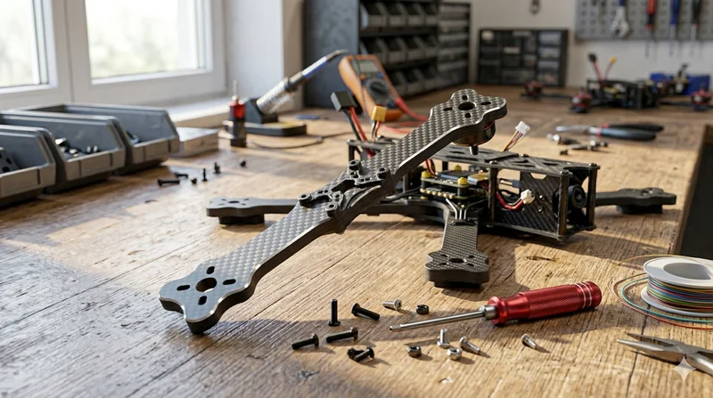
Carbon Fiber Drone Arm
Precision-molded carbon fiber drone arm combining unidirectional fiber for stiffness and woven layers for torsional strength. Designed for FPV, photography, and industrial drone platforms. Each arm is CNC-machined to exact specifications.