
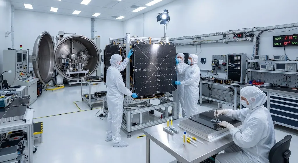
Every satellite is a thermal machine: payload electronics generate heat, and in the vacuum of space that heat can leave the spacecraft only by radiation. The radiator panel is the component that carries waste heat to a radiating surface and emits it to deep space, and it must do so whil
Introduction
Every satellite is a thermal machine: payload electronics generate heat, and in the vacuum of space that heat can leave the spacecraft only by radiation. The radiator panel is the component that carries waste heat to a radiating surface and emits it to deep space, and it must do so while also serving as primary structure, holding dimensional stability on precision instruments, and adding as little mass as possible. For decades aluminum panels did the job. As satellite power levels climb — high-throughput telecommunications satellites now dissipate multiple kilowatts — carbon fiber radiator panels have become the weight-saving standard on modern spacecraft buses.
This article covers the physics behind space radiators, why carbon fiber is uniquely suited to them, how high-thermal-conductivity fiber differs from standard structural fiber, and how panels are designed, integrated, and qualified for orbital service.
Why Radiators Dominate Spacecraft Thermal Design
In orbit, conduction and convection have nowhere to go: the only heat rejection path is radiation, which follows the Stefan-Boltzmann law — radiated power scales with the fourth power of absolute temperature. A spacecraft radiator therefore has a fixed budget: given a maximum allowed temperature at the heat source, the panel area must be large enough to radiate the payload heat load at that temperature. Because the fourth-power law is steep, a few degrees of allowed temperature rise can shrink the required radiator area substantially, but payload electronics are temperature-constrained, so engineers instead work to spread heat evenly and radiate it as efficiently as the area allows.
Two design consequences follow. First, the radiator must collect heat from distributed sources — transponders, batteries, power conditioning units — and spread it across the full panel surface, which demands high in-plane thermal conductivity in the facesheet. Second, the panel must reject that heat from both faces where possible, which drives panel topology and coatings. The facesheet is thus the heart of the panel: if it conducts poorly, hot spots form, efficiency drops, and the required area grows.
Why Carbon Fiber Wins on Conductivity Per Kilogram
| Material | Typical in-plane conductivity | Density | CTE | Key trade-off |
|---|---|---|---|---|
| Aluminum 6061 facesheet | ~167 W/(m·K) | 2.7 g/cm³ | ~23 ppm/K | Cheap, most qualified, heavy, high CTE |
| Standard PAN carbon fiber | ~5-10 W/(m·K) | 1.6 g/cm³ | Near zero | Light and stiff but thermally insulating |
| High-modulus PAN fiber | ~40-90 W/(m·K) | 1.7 g/cm³ | Slightly negative | Moderate conductivity, good strength |
| Pitch-based fiber (K13D class) | 400-800 W/(m·K) fiber | 2.0 g/cm³ | Negative | Superb conductivity, higher cost |
| Carbon-carbon radial fin | up to 300 W/(m·K) in-plane | 1.8 g/cm³ | Low | High temperature capable, complex |
Standard PAN-based carbon fiber is a thermal insulator in the plane — around 5-10 W/(m·K) in a laminate — yet it is the strongest, stiffest, and cheapest aerospace fiber. High-modulus PAN grades raise conductivity into the 40-90 W/(m·K) range with near-zero CTE, adequate for many panels. Pitch-based fibers, derived from petroleum pitch rather than polyacrylonitrile, reach astonishing fiber-level conductivities of 400-800 W/(m·K), and composite facesheets built from them deliver in-plane values of 150-300 W/(m·K) — comparable to aluminum at roughly 60-70% of the weight.
The density comparison is the crux: aluminum at 2.7 g/cm³ against carbon fiber composites near 1.6-1.7 g/cm³. A carbon facesheet can match aluminum's conductance with lower mass, or exceed it at equal mass, and the CTE stays near zero instead of 23 ppm/K. For satellites, where every kilogram of bus mass costs payload mass, this combination is decisive.
Panel Architecture and Thermal Integration
A practical carbon fiber radiator is a sandwich: thin conductive facesheets bonded to a light honeycomb core by a thermally conductive film adhesive. The outer facesheet carries the radiating coating and the in-plane conduction; the core provides bending stiffness; the inner facesheet interfaces with equipment panels. The facesheet layup is tailored per application — structural PAN plies for strength, high-conductivity pitch plies on the surface for heat spreading, with ply sequences arranged to keep CTE near zero in both panel directions.
- Heat pipes and thermal doublers: most panels embed aluminum heat pipes below equipment mounting feet; carbon doublers spread heat from concentrated sources into the facesheet before it reaches the pipes.
- Radiating coating: the outer surface needs high emissivity in the infrared; white paints, silvered Teflon, or optical solar reflectors balance heat rejection with solar absorption on sunlit faces.
- Adhesive selection: the film adhesive must transfer heat across the facesheet-core bond; thermally loaded adhesives with good conductivity and outgassing performance are standard.
- Grounding and protection: carbon facesheets need conductive grounding paths and lightning or arcing protection appropriate to the orbit environment.
Thermal integration is where radiator performance is really won or lost: a perfectly conductive facesheet still underperforms if the adhesive bond is porous, if heat pipes end short of the heat source, or if the radiating coating degrades under ultraviolet exposure.
Manufacturing and Qualification for Space
Space radiator panels are manufactured like precision aerospace sandwich structures and then qualified against the space environment. Layup is typically autoclave prepreg processing with tight fiber alignment control, followed by non-destructive inspection of the facesheet-core bond. Core is usually aluminum honeycomb for proven bonding and thermal behavior, though aramid and thermoplastic cores appear where mass or specific stiffness dominates.
- Thermal vacuum testing: panels cycle between hot and cold extremes under vacuum, validating radiative performance and exposing entrapped moisture and outgassing.
- Thermal cycling: hundreds of cycles across the service temperature range verify facesheet-core bond integrity and CTE stability.
- Outgassing control: total mass loss and collected volatile condensable materials are measured per NASA or ESA standards to protect optics and sensors.
- Vibration and acoustic testing: launch loads must not delaminate facesheets or crack heat pipe attachments; sine, random, and acoustic qualification follows the launch vehicle envelope.
- CTE verification: near-zero CTE is validated by interferometric measurement across the operating range so precision payload alignment survives orbit thermal swings.
Qualification follows the same logic as any spacecraft structure: analytical models supported by coupon tests at the material level, panel-level verification of thermal and structural functions, and full-article testing against the launch and on-orbit environments.
Frequently Asked Questions
Why use carbon fiber for radiator panels when aluminum conducts heat better?
Aluminum does conduct heat well, and it remains the baseline for radiator design — but carbon fiber wins on the mass and stability side. A pitch-based or high-modulus carbon facesheet can reach 150-300 W/(m·K) in-plane conductivity at roughly 60-70% of the weight of an aluminum facesheet, and its near-zero CTE prevents the thermal distortion that 23 ppm/K aluminum panels impose on precision payloads. On many spacecraft, the mass saved on radiators converts directly into additional payload, which is why carbon radiators now appear on high-value geostationary and Earth-observation platforms.
What is the difference between pitch-based and PAN-based carbon fiber for thermal applications?
PAN-based carbon fiber is derived from polyacrylonitrile precursor and is the default structural aerospace fiber: strong, stiff, well documented, but thermally insulating in a laminate (roughly 5-10 W/(m·K) in-plane; high-modulus PAN grades reach 40-90 W/(m·K)). Pitch-based fiber is made from petroleum pitch and oriented so highly that fiber thermal conductivity reaches 400-800 W/(m·K); composites from it deliver in-plane conductivity comparable to or better than aluminum. Pitch fibers cost more, have lower compressive strength and strain-to-failure, and require a slightly different layup and handling philosophy, so panels commonly use them only for the conductive surface layers over structural PAN plies.
How much weight can carbon fiber radiator panels save on a satellite?
Savings depend on panel size and architecture, but carbon radiators typically weigh 30-50% less than the all-aluminum baseline for the same thermal performance. The facesheet mass drops by about a third because conductivity matches aluminum at lower density, and the core and adhesive stay common to both designs. On a three-tonne geostationary satellite with several square metres of radiator area, the saving can reach tens of kilograms — enough to add payload or propellant. The exact number depends on fiber grade, layup, coating, and how aggressively the design optimizes the thermal path.
Conclusion
Carbon fiber space radiator panels solve the central tension of spacecraft thermal design: rejecting kilowatts of heat with the least possible mass and no thermal distortion. Pitch-based and high-modulus carbon facesheets deliver aluminum-class conductivity at substantially lower density while holding near-zero CTE, and the sandwich construction carries structural loads as part of the bus. As satellite power densities grow, the technology is moving from specialist geostationary platforms into constellations, small satellites, and high-power electric propulsion spacecraft.
For satellite builders and thermal engineers, the path starts with the right fiber grade: high-modulus PAN for balanced panels, pitch-based fiber for conduction-critical heat-spreading layers, and careful attention to adhesive and coating choices that complete the thermal path. Explore our carbon fiber products for high-thermal-conductivity and space applications, or contact our engineering team to discuss material selection for your spacecraft thermal architecture.
Part of topic
Related Articles
- Carbon Fiber Sheets for Sale: A Buyer Checklist for Thickness, Weave and Finish
- Carbon Fiber Plate Running Shoes: Manufacturing Process and Material Specifications
- Carbon Fiber Tubes for Sale: Spec Sheet Fields That Actually Matter
- Carbon Fiber Sheets Near Me: Local Dealers and Quick Turnaround Procurement
- Carbon Fiber Tubes Near Me: Local Stock Availability and Same-Day Delivery Options
- Carbon Fiber Plate Orthotic: Lightweight Prosthetic and Medical Device Applications
Interested in Our Products?
Contact our team for competitive pricing and technical specifications.
Get a QuoteRelated Products

Carbon Fiber Plate — 3K Twill T700 1.5mm
Thin 1.5mm carbon fiber plate with 3K twill weave surface. Lightweight and stiff, commonly used for covers, panels, drone bodies, and applications requiring a premium aesthetic appearance.

Carbon Fiber Plate — 3K Twill T700 3.0mm
Medium-thickness 3.0mm carbon fiber plate offering significantly higher load capacity while maintaining attractive 3K twill finish. Suitable for structural brackets, reinforcement plates, and load-bearing panels.

Square Carbon Fiber Tube — 3K Twill T700
Square cross-section carbon fiber tube manufactured with 3K twill weave for torsional strength. Preferred for structural frames, trusses, and support columns where rectangular geometry offers design flexibility.

Carbon Fiber Plate — UD Unidirectional T700
Unidirectional carbon fiber plate with all fibers oriented in a single direction for maximum strength along the fiber axis. Essential for structural reinforcements, splints, and applications where load direction is predictable.

Round Carbon Fiber Tube — UD Unidirectional T700
Unidirectional (UD) round tube with all fibers aligned axially for maximum longitudinal stiffness. Ideal for applications requiring high bending rigidity with minimal weight, such as shafts, struts, and structural reinforcements.