
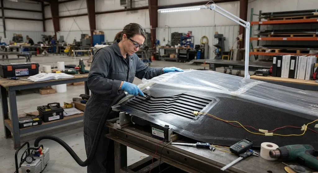
Scarf-bonded repair is the preferred method for restoring load-carrying carbon fiber structures — aircraft skins, rotor blades, boat hulls and pressure vessels — because it returns the part to near-original strength with a minimal weight penalty and a barely visible footprint. Instead o
Introduction
Scarf-bonded repair is the preferred method for restoring load-carrying carbon fiber structures — aircraft skins, rotor blades, boat hulls and pressure vessels — because it returns the part to near-original strength with a minimal weight penalty and a barely visible footprint. Instead of overlapping a patch on the surface, a scarf repair tapers the damaged material away in a shallow cone and bonds in a matching tapered patch, so the load transfers through a continuous adhesive bondline rather than through fasteners or a thick external doubler. The result looks and behaves like the original laminate: aerodynamic, low-profile, and structurally continuous.
The engineering that makes a scarf repair sound in practice sits in three decisions: the scarf ratio — the length of taper per unit of laminate depth — which sets how much strength can be recovered; the conversion of that smooth taper into a machined or hand-laid stepped geometry that is actually achievable in a workshop; and the bondline assurance package — surface preparation, vacuum, cure and inspection — that confirms the adhesive actually carries the load it is trusted with. This article walks through each and gives the numbers that repair engineers and buyers use to judge a repair program.
Scarf Ratio Selection and Strength Recovery
The scarf ratio is the slope of the taper: a 30:1 ratio means the taper runs 30 mm of length for every 1 mm of laminate thickness. The ratio controls how gradually the load is transferred from the parent laminate into the patch through the adhesive. A shallow, long scarf spreads the shear stress over a large bondline and keeps the peak stress low; a steep, short scarf concentrates the load transfer into a small region and drives the peak stress toward the adhesive's strength limit. The aerospace baseline is well established, and it reflects the mechanics:
| Scarf Ratio | Typical Use | Expected Strength Recovery | Notes |
|---|---|---|---|
| 20:1 | Lightly loaded secondary structures | 70-85 percent | Rarely used for primary structure; steep for bonded repair |
| 30:1 | General aerospace structural repair | 85-95 percent | Common baseline for thin laminates |
| 40:1 | Primary structure, higher-loaded regions | 90-98 percent | Preferred where load concentration matters |
| 50:1 to 60:1 | Compression-critical and thick laminates | 95-100 percent | Baseline for heavily loaded CFRP in compression |
The reason the ratio matters so much is shear-lag. In a bonded joint, the load enters the adhesive at the ends of the overlap and decays toward the middle; peak shear stress appears at the scarf tips. Lengthening the scarf spreads that peak over a bigger area and lowers its magnitude, which is why shallow ratios recover nearly full strength. There is a practical boundary, however: beyond roughly 60:1, the strength gain per additional millimeter of taper becomes small, the machining becomes delicate, and the repair footprint grows into neighboring structure. Most repair manuals therefore cap the design ratio near 50-60:1 and reach full recovery through surface quality rather than ever-longer tapers.
Stepped Scarfing: The Practical Equivalent of the Smooth Taper
A true smooth scarf is machined with a rotating cutter on a rigid fixture and is practical for thin skins and flat areas. On thick laminates, in curved regions and on site, a smooth conical taper is hard to machine accurately, so repair shops use the stepped scarf instead: the laminate is routed out in a series of concentric steps, each step removing one or two plies, and the patch is built with matching stepped plies bonded together. The stepped geometry is a staircase approximation of the smooth taper, and its mechanical behavior converges to the smooth scarf when the steps are thin enough relative to the local thickness.
The equivalence is not automatic. Each step edge is a local stress concentration, and the layup of the stepped patch must mirror the parent laminate ply-by-ply so the load path is continuous. Two rules keep the approximation sound: first, the step depth should nominally equal the ply thickness of the parent laminate so each new step lands on a real ply boundary; second, the step width follows the scarf ratio projected onto the stepped profile. A 40:1 ratio on a 4 mm laminate with 0.2 mm plies produces roughly 20 steps, each about 8 mm wide — a geometry that hand layup carries out without special tooling.
| Parameter | Guideline |
|---|---|
| Step depth | Equal to one ply thickness (0.13-0.25 mm typical) |
| Step width | Ratio times step depth (for 40:1, about 40 x step depth) |
| Number of steps | Laminate thickness divided by step depth |
| Scarf angle accuracy | Plus or minus 0.5 degree on the taper plane |
| Surface finish | Uniform, no burns, no torn fibers at step edges |
Machining quality controls the outcome directly. A router cutter that tears fibers at the step edge leaves a damaged substrate that becomes a starting crack in the repaired zone. Wet or dry grinding, burr-free routing with proper feeds and speeds, and final manual clean-up with fine abrasive are the accepted sequence. In production repair shops, the stepped scarf is cut on CNC-controlled equipment guided by the original ply map, which guarantees the step positions land on real ply boundaries rather than mid-ply.
Surface Preparation and Adhesive Selection
Strength recovery in a bonded repair is limited by the weakest link, and for modern toughened adhesives the weak link is usually the interface between the adhesive and the prepared substrate, not the adhesive itself. Surface preparation therefore decides more of the outcome than the adhesive grade. The sequence that aerospace repair manuals converge on is: remove contamination with solvent, abrade the bonded surface to a controlled roughness, dry the surface, and bond within a specified time window because the activated surface loses its receptive state with atmospheric exposure. The abrasion must be uniform — patchy roughness produces patchy bond strength — and the surface must be free of dust, moisture and release agents.
Adhesive selection follows the operating environment and the cure available in the workshop. Film adhesives laid with the patch on a vacuum bag are the standard for repair because they flow under pressure and give a controlled bondline thickness; paste adhesives are used for filleting, edge sealing and smaller repairs. Cure temperature drives the scheduling: a 120 °C cure film gives higher hot-wet performance but requires a repair blanket or oven, while a 70-80 °C cure system is field-friendly and adequate for many structures. Toughened epoxy systems are preferred for primary structure because they tolerate peel and impact loads that a brittle adhesive would transfer into the laminate as delamination.
- Solvent wipe: Remove grease, release residues and dust before any abrasion.
- Controlled abrasion: Uniform roughness across the full scarf area, verified by contact-angle or water-break test.
- Vacuum dry: Remove absorbed moisture before cure; moisture trapped at the bondline becomes porosity under heat.
- Time discipline: Bond within the manufacturer's open time; prepare in batches that match the cure schedule.
- Adhesive match: Film thickness and cure temperature matched to the part service temperature and the available cure equipment.
Bondline Assurance: Vacuum, Cure and Nondestructive Inspection
The final layer of engineering is proving the bondline exists and carries load. Vacuum is the first control: the repair area is bagged and drawn down to a target vacuum, typically minus 0.85 bar or better, which consolidates the patch to the taper and applies the consolidation pressure that film adhesives need to wet the surface. The vacuum must be verified before cure and maintained during it; a leaking bag at cure temperature is the classic cause of a porous bondline discovered at inspection.
Cure control means instrumenting the bondline — thermocouples on the patch surface and, where possible, at the bondline — and following the adhesive manufacturer's heat-up rate, dwell and cool-down. The most common repair failures are not under-cure but uneven cure: hot spots from an uncalibrated blanket or cold zones at the repair edge leave a partially cured adhesive that passes glancing inspection and fails in service. After cure and demolding, the repaired region is inspected by nondestructive methods — dry-contact ultrasonic or phased-array scanning being standard for bonded repairs — to confirm there is no porosity, no disbond, and no gap at the step edges. Acceptance is gated on the scan record, not on visual appearance, because a scarf repair that looks perfect can hide a bondline void that will grow under fatigue.
Documentation closes the loop. A certified repair is traceable: the damage assessment, the scarf geometry, the material system, the cure record and the NDI results form a repair dossier that the structure's continuing-airworthiness records carry. Buyers and operators evaluating a repair provider should look for this dossier discipline, because it is the only evidence that the ratio, the steps and the bondline were actually engineered and verified rather than improvised.
Frequently Asked Questions
Why is 30:1 the most common scarf ratio for aerospace repairs?
The 30:1 baseline reflects the balance between strength recovery and practical geometry. At 30:1, shear-lag analysis shows that the peak adhesive stress drops low enough to recover 85-95 percent of the undamaged laminate strength for typical structural layups, while the taper stays short enough to machine accurately without a large repair footprint. Heavier-loaded regions and compression-critical laminates are pushed to 40:1 or beyond, where certified programs demonstrate 95 percent and higher recovery in mechanical testing.
Can a scarf repair be made stronger than the original laminate?
Not meaningfully, and the attempt is not the goal. The scarf joint is a bonded interface, so its strength is bounded by the adhesive-to-substrate shear strength; the best-case outcome is approaching the parent laminate's strength, typically 90-100 percent recovery with high-ratio scarfs and excellent surface preparation. Repair acceptance criteria are written as a percentage of the original design strength, and designs keep the repair zone load below that recovered value rather than aiming to exceed the parent material, which would simply move the failure location.
What causes a scarf repair to fail despite correct ratio and materials?
The classic root causes are contamination, moisture and cure inconsistency rather than the ratio. A solvent-wiped surface re-contaminated by handling or dust bonds poorly at the interface. Moisture absorbed into the substrate vaporizes during cure and leaves porosity along the bondline. An uneven cure — cold zones, overshoot, or a leaking vacuum bag — produces a partially cured or porous adhesive. Each of these is invisible to the eye and detected only by disciplined surface preparation, vacuum verification, thermocouple-monitored cure and final ultrasonic inspection.
Conclusion
Scarf-bonded repair restores damaged carbon fiber structures to near-original strength when three disciplines are held together: a scarf ratio chosen from the load case and laminate thickness — 30:1 for general structural repair, deeper toward 50-60:1 for compression-critical and thick sections; a stepped scarf machined so each step lands on a real ply boundary; and a bondline assurance package of surface preparation, vacuum, instrumented cure and ultrasonic inspection that proves the bond before the part returns to service. The ratio is the design, the steps are the execution, and the inspection is the proof. Repairs that hold together do so because all three were engineered as one system.
YongXian supplies carbon fiber fabrics, unidirectional prepreg and repair-grade reinforcement materials used in scarf-bonded and other bonded repair programs across aviation, marine, wind energy and industrial structures. Explore our carbon fiber product range or contact our engineering team to discuss repair-material systems, ply-matched fabrics and prepreg cure support for your maintenance and overhaul operation.
Related Articles
- Bio-Based Carbon Fiber Precursors: Lignin and Polyethylene for Low-Cost Production
- Large-Tow Carbon Fiber Cost Analysis: 48K vs 60K Price-Performance Comparison
- Carbon Fiber-Resin Interface Bonding: Surface Treatment and Coupling Agent Optimization
- Digital Twin for Carbon Fiber Manufacturing: Real-Time Process Monitoring and Defect Prevention
- Thermoplastic Carbon Fiber Welding for Automotive: Ultrasonic and Induction Welding Process Windows
- Large-Tow Carbon Fiber Wet Spinning: Process Optimization for 48K/60K Production Efficiency
Interested in Custom Carbon Fiber Products?
Contact our team for competitive pricing and technical specifications.
Get a QuoteRelated Products

Carbon Fiber Fishing Rod Blank
High-quality carbon fiber fishing rod blank manufactured from multiple grades of Toray carbon fiber cloth. Available in a wide range of lengths, powers, and actions for freshwater and saltwater applications. Suitable for OEM rod building.
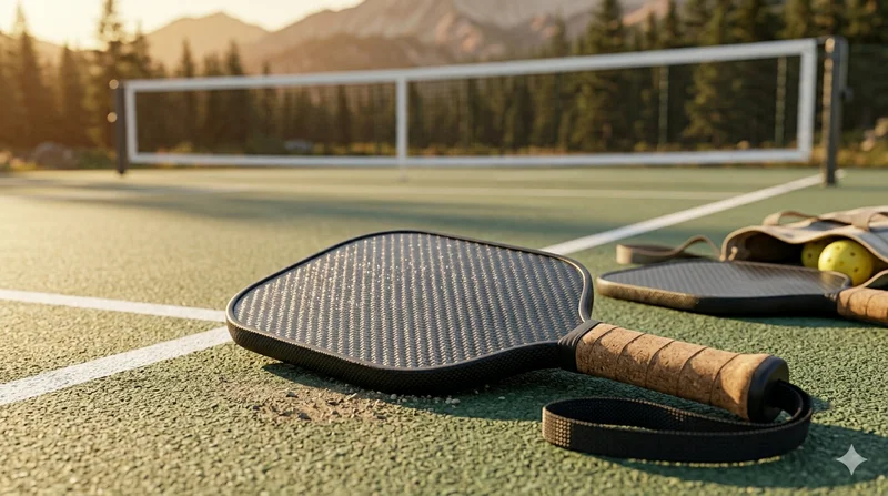
Carbon Fiber Pickleball Paddle
High-performance pickleball paddle with Toray T700 carbon fiber face and polypropylene honeycomb core. Delivers excellent power-to-weight ratio, spin generation, and vibration dampening for competitive play.
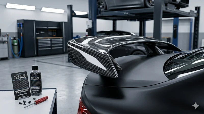
Carbon Fiber Automotive Spoiler
Automotive-grade carbon fiber spoiler manufactured using autoclave-cured pre-preg technology. Each spoiler is vacuum-bagged and oven-cured for optimal fiber-to-resin ratio, strength, and a flawless cosmetic finish.
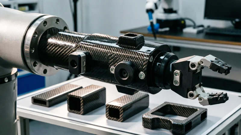
Carbon Fiber Robot End Effector Link — Custom Shape & Sensor Integration
Custom-shaped carbon fiber end effector links for robotic arms. Designed for automation integrators and research labs requiring lightweight, rigid connections between the robot wrist and gripper/tool. Can incorporate sensor mounting bosses, cable routing channels, and quick-change interfaces.

Custom Carbon Fiber Medical Device Components
Medical-grade carbon fiber components manufactured for imaging equipment, surgical instruments, and patient support systems. Carbon fiber's radiolucency (X-ray transparency) and high strength-to-weight ratio make it ideal for CT scanner beds, wheelchair frames, surgical robot arms, and MRI-compatible accessories. Biocompatible resin systems available.