
Resin transfer molding has become the standard route for medium-to-high-volume carbon fiber parts — automotive structural components, aerospace secondary structures, bicycle frames, and industrial parts — because it combines near-net-shape geometry, Class-A or engineering surfaces on bo
Introduction
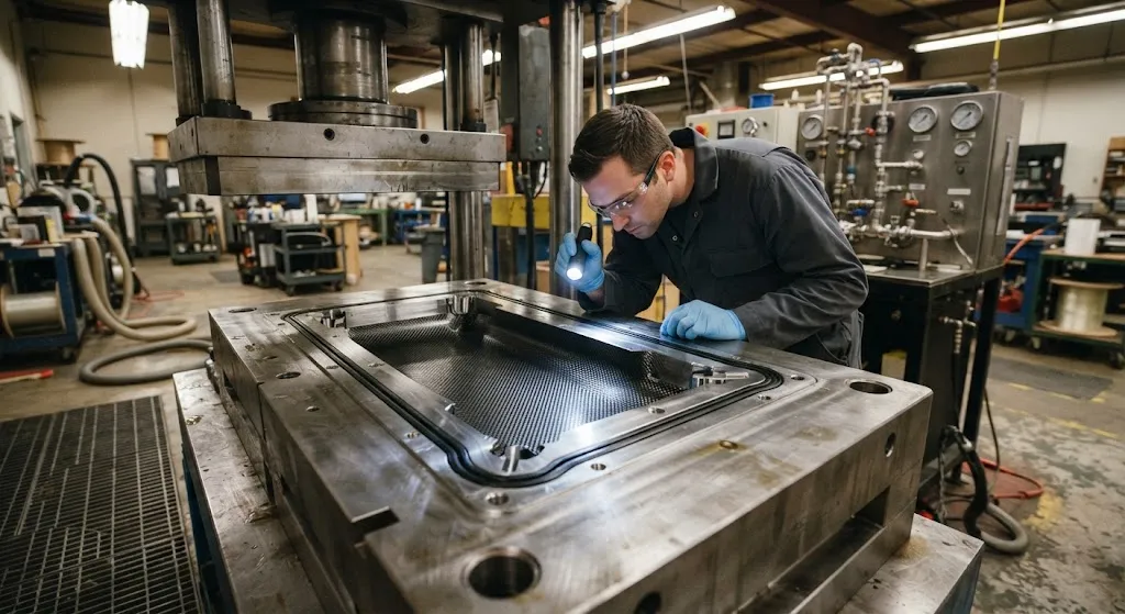
Resin transfer molding has become the standard route for medium-to-high-volume carbon fiber parts — automotive structural components, aerospace secondary structures, bicycle frames, and industrial parts — because it combines near-net-shape geometry, Class-A or engineering surfaces on both sides, and cycle times measured in minutes rather than hours. The process injects low-viscosity resin into a closed mold cavity that already contains the dry fiber preform; once cured, the part is demolded with minimal trimming. The attraction is obvious. The difficulty is that the mold is the product: any leak, misplaced gate or wrongly positioned vent turns a repeatable process into a lottery.
This article focuses on the three engineering decisions that dominate RTM tooling performance: how the seal system is designed so it does not leak or flash, where the injection gates and vents are placed so the cavity fills completely, and how compression tolerance is achieved so the part thickness and fiber volume fraction come out right. These are the decisions that separate molds which run thousands of cycles from molds which are re-engineered every month.
Why RTM Seals Fail and Where Dry Spots Come From
Seal failure in RTM is one of the most common sources of scrap, and it shows in two ways. The first is leakage — resin escapes between the mold halves, either flashing out at the parting line or being drawn into the vacuum system, which starves the cavity of the very resin the part needs. The second is incomplete fill without visible leakage: air is trapped in the cavity because the seal is too tight in one zone and the vent is not where the air actually collects. Both failure modes share a root cause: the seal system was designed as an afterthought rather than as part of the flow path.
Dry spots — regions of the laminate where no resin arrived — are the physical result. They form at the last-filled points of the cavity, typically at corners, ribs, inserts and thickness transitions, wherever the flow front has to change direction or where the preform permeability drops locally. The permeability of the fiber preform is not uniform: a compressed edge, a folded tow bundle or a ply overlap creates a low-permeability zone that the resin bypasses, leaving a dry patch behind. The geometry of the tool, not the resin, therefore dictates where the vents must be, and the vents must sit exactly where air is predicted to accumulate last.
Injection Gates and Vent Placement
Gate placement defines the fill pattern, and the fill pattern defines the dry-spot risk. In production RTM, three gate strategies dominate. Center-gated injection pushes resin from a single point outward to the edges, giving a radial flow front that is the most forgiving of preform variation; it suits flat panels and parts with a central boss. Edge and perimeter gating inject along one side or around the circumference, forcing a more linear flow front that is faster but more sensitive to permeability differences across the preform. Sequential or multi-point gating opens gates in a timed sequence so the flow front is steered around inserts and difficult zones; this is the strategy for complex geometries with ribs, cores and metallic inserts, and it is increasingly implemented with a pressure sensor at each gate.
Vent placement is the mirror image of gate placement. Vents must sit at the last-filled points — the positions the flow front reaches only at the end of fill, where air has nowhere to go but out. The table below summarizes the practical rules that experienced tool engineers use:
| Design Question | Recommended Practice | Reason |
|---|---|---|
| Vent location | At corners, rib ends, inserts and other last-filled points | Air accumulates at the end of the flow front |
| Vent type | Groove vent with O-ring seal around it, open to vacuum | Allows air out, seals resin in once fill completes |
| Vent spacing | Every 50-150 mm along long edges | Prevents air pockets between widely spaced vents |
| Gate-to-vent ratio | Typically 1 gate per 2-4 vents for symmetric parts | Ensures the flow front is pushed rather than pulled |
| Flow simulation | Run mold-filling simulation before cutting steel | Predicts last-filled points and validates vent layout |
Modern HP-RTM tools take this further: they instrument the cavity with pressure transducers at the last-filled points and integrate a "vent check" — a sensor that confirms resin has actually arrived at each vent before the injection pressure ramps. This closes the loop between fill control and part quality, because a vent that received resin proves that the flow front traversed the whole cavity rather than bypassing a dry patch.
Seal Design and Compression Molding Tolerance
The seal system in an RTM tool has a dual role: it must contain the resin during injection and it must allow the mold to close to a precise final thickness. These two roles pull in opposite directions, which is why seal design is a real engineering discipline rather than a catalog pick. Elastomeric O-rings are the workhorse — they seal reliably at pressures up to several tens of bar, tolerate the part geometry, and are replaceable — but they compress under closure and their compression set over thousands of cycles changes the effective parting-line height. That drift changes the cavity thickness, which changes the part's fiber volume fraction, which changes the mechanical performance. A tool signed off at 60 percent fiber volume in month one can silently drift to 58 percent by month nine.
Compression molding tolerance is therefore managed on two levels. The first is the closure system itself: hydraulic or mechanical stops built into the tool, precision-ground spacer blocks, and a press with controlled closing force so the mold halves seat at exactly the same position every cycle. The second is the sealed peripheral zone: rather than trusting the elastomer to hold a precise height, production tools use a positive-stop arrangement where metal-to-metal contact — a machined land outside the seal groove — takes the closure load, and the O-ring only has to seal, not to carry the press force. This separation of duties is the single most important detail in durable RTM tooling: the seal is never crushed to tolerance, and the tolerance is never dependent on seal elasticity.
| Seal Type | Pressure Rating | Compression Tolerance | Life Expectancy | Typical Use |
|---|---|---|---|---|
| Elastomeric O-ring (NBR/Viton) | 10-50 bar | ±0.05-0.1 mm fresh, drifts with age | 500-2,000 cycles | General RTM parting line |
| O-ring + metal hard-stop land | 10-70 bar | ±0.02-0.05 mm, stable | With seal replacement | Production HP-RTM tools |
| Machined close-tolerance seal groove | Up to 100 bar with high-clamp presses | ±0.01-0.03 mm | Tool lifetime | High-volume, precision parts |
| Vacuum-bag edge seal (peripheral) | Low pressure, vacuum only | Not load-bearing | Per use | Vacuum-assisted RTM variants |
The tolerance story closes with the press and the process window. HP-RTM at injection pressures of 60-120 bar demands a stiff press and a tool that does not flex, because any deflection changes the cavity thickness under pressure. Thermal management adds the last constraint: steel and aluminum tool materials expand differently, so a tool designed for a 100 °C cure must have its seals, stops and gate locations validated at that temperature. Warpage and seal extrusion at operating temperature are classic first-run failures that only show up after the tool is already in service.
Practical Design Rules for First-Pass Molds
Compiling the experience of mature RTM shops into design rules keeps first tools off the scrap heap. The rules below are not exhaustive, but they catch the majority of avoidable failures:
- Simulate before cutting steel: Run mold-filling simulation on the preform permeability, not the cavity alone, and place vents at the predicted last-filled points.
- Separate sealing from tolerancing: Use machined hard-stop lands to carry closure load and let the O-ring only seal; never let seal compression define part thickness.
- Vent at every geometric trap: Ribs, cores, inserts and thickness steps each deserve their own vent; a single perimeter vent is insufficient for anything but flat panels.
- Instrument the last-filled points: Pressure or flow sensors at the vents let the controller confirm complete fill, which converts inspection from post-cure ultrasonic to in-process certainty.
- Validate at operating temperature: Check seal fit, gate sealing and mold closure at the actual cure temperature, where thermal expansion changes all clearances.
Each rule has a documented failure behind it. Shops that skip simulation find dry spots at first injection; shops that let seals carry closure load watch thickness drift across the tool's life; shops that vent only at the edge chase air pockets in rib corners for months. The tooling budget spent on these rules is the cheapest insurance in the entire RTM process.
Frequently Asked Questions
How many injection gates does an RTM part typically need?
There is no universal number — it depends on part size, geometry and cycle-time target. A flat panel up to roughly a meter across fills reliably from a single center or edge gate. Parts with ribs, inserts or large area variations typically need multiple gates in a sequential injection scheme, steered by pressure sensors, so the flow front can be controlled around the difficult zones. As a starting rule, simulate the fill; the simulation will show whether one gate produces an acceptable fill time and a dry-spot-free flow front before any steel is cut.
Why do dry spots keep appearing at the same location in every part?
A dry spot that repeats at a fixed location is almost always a geometry-permeability interaction: the preform is compressed or folded at that point, the local permeability drops, and the resin flow front bypasses the zone. The solution is not more injection pressure — it is investigating the preform at that location (folded tow, ply overlap, compressed edge), verifying that the vent actually sits at that last-filled point, and checking whether the seal or an insert is blocking the flow path. In-process vent sensors will confirm whether resin arrives there at all, which separates a fill problem from a preform problem.
Can an elastomeric O-ring hold HP-RTM injection pressures?
Modern elastomeric O-rings are specified for HP-RTM pressures in the 60-120 bar range when they sit in properly machined grooves with enough gland fill. The failure mode to design against is extrusion — resin pressure forcing the elastomer out of its groove — which is prevented by correct groove geometry, adequate gland support and backup rings if needed. The bigger reliability risk is not the seal's pressure rating but compression set over thousands of cycles, which is why production tools use sacrificial, replaceable seals in conjunction with metal hard stops that carry the actual closure load.
Conclusion
RTM tooling is where the process is won or lost. Seal systems must contain pressure and leak nothing while separate hard-stop arrangements carry the closure tolerance; gates must steer a flow front that reaches every corner; and vents must sit at the last-filled points where air would otherwise be trapped. Simulating the fill on realistic preform permeability, instrumenting the vents to confirm complete fill, and validating the whole assembly at operating temperature turn RTM from a process that occasionally produces dry spots into one that produces them almost never. The tooling is the product, and it is worth engineering like one.
YongXian supplies carbon fiber fabrics, unidirectional reinforcements and multiaxial preforms suitable for RTM, HP-RTM and vacuum-infusion molding across automotive, aerospace and industrial programs. Explore our carbon fiber product range or contact our engineering team to discuss reinforcement formats, permeability-matched fabrics and custom preform support for your molding process.
Part of topic
Related Articles
- Bio-Based Carbon Fiber Precursors: Lignin and Polyethylene for Low-Cost Production
- Large-Tow Carbon Fiber Cost Analysis: 48K vs 60K Price-Performance Comparison
- Carbon Fiber-Resin Interface Bonding: Surface Treatment and Coupling Agent Optimization
- Digital Twin for Carbon Fiber Manufacturing: Real-Time Process Monitoring and Defect Prevention
- Thermoplastic Carbon Fiber Welding for Automotive: Ultrasonic and Induction Welding Process Windows
- Large-Tow Carbon Fiber Wet Spinning: Process Optimization for 48K/60K Production Efficiency
Interested in Custom Carbon Fiber Products?
Contact our team for competitive pricing and technical specifications.
Get a QuoteRelated Products
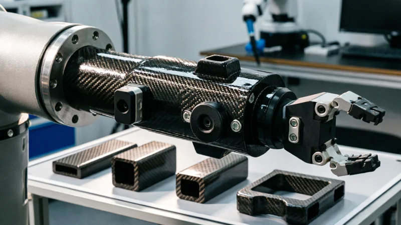
Carbon Fiber Robot End Effector Link — Custom Shape & Sensor Integration
Custom-shaped carbon fiber end effector links for robotic arms. Designed for automation integrators and research labs requiring lightweight, rigid connections between the robot wrist and gripper/tool. Can incorporate sensor mounting bosses, cable routing channels, and quick-change interfaces.

Custom Carbon Fiber Medical Device Components
Medical-grade carbon fiber components manufactured for imaging equipment, surgical instruments, and patient support systems. Carbon fiber's radiolucency (X-ray transparency) and high strength-to-weight ratio make it ideal for CT scanner beds, wheelchair frames, surgical robot arms, and MRI-compatible accessories. Biocompatible resin systems available.

Custom Carbon Fiber Musical Instrument Parts
Carbon fiber components for musical instrument manufacturing offering superior dimensional stability, low weight, and consistent acoustic properties. We produce carbon fiber bows, guitar necks, violin chin rests, drum shells, and wind instrument bodies. Carbon fiber instruments are immune to humidity changes and temperature fluctuations that affect wooden instruments.

Carbon Fiber Tablet Case — Ultra-Light Protective Shell
Lightweight carbon fiber protective case for tablets and iPads. Molded from T700 3K prepreg with reinforced corner protection. Adds minimal weight while providing superior rigidity and drop protection compared to polycarbonate or silicone cases. Ideal for field workers, enterprise deployments, and professionals requiring durable tablet protection.
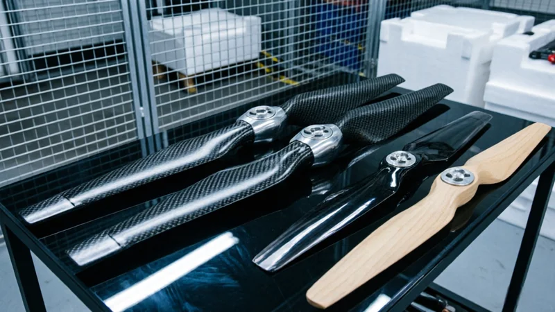
Carbon Fiber Drone Propeller — High-Performance Prepreg Molded
Prepreg-molded carbon fiber propellers for industrial and racing drones. Optimized airfoil design with balanced blade geometry for maximum thrust efficiency. 3-5× stiffer than nylon/plastic props, reducing blade flutter and improving flight stability. Available in common sizes or custom diameter/pitch.