
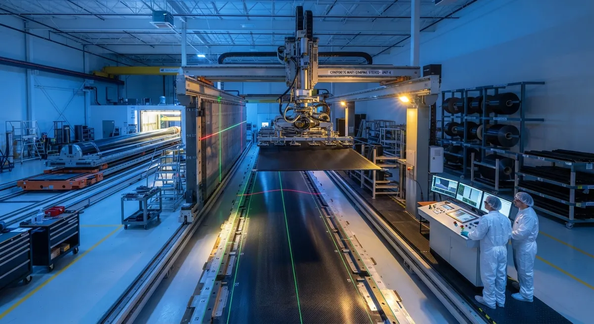
A 70-meter carbon fiber mast cannot be laid up by hand. The plies are too large, the required positional accuracy too tight, and the working envelope beyond what a crew of laminators can reach consistently. That simple constraint is driving large-part composite manufacturers toward robo
Introduction
A 70-meter carbon fiber mast cannot be laid up by hand. The plies are too large, the required positional accuracy too tight, and the working envelope beyond what a crew of laminators can reach consistently. That simple constraint is driving large-part composite manufacturers toward robotic draping and mold automation: cells in which robots pick pre-cut fabric plies, drape them onto molds with controlled compaction, and hand the finished preform to the next station with position data logged for every ply. This article explains how these Fives-style cells work, compares them with manual layup and automated fiber placement, and reviews the production results that are making them standard for masts, blades, and ship structures.
What Robotic Draping Cells Do
A robotic draping cell replaces the laminator's hands, not the laminator's judgment. The core elements are consistent across installations:
- Automated cutting and kitting: Fabric is cut on an automated cutting table with nesting software, and plies are kitted with barcode labels identifying part, layer, and orientation.
- Robotic pick-and-place draping: A gantry or articulated robot collects each ply using a custom end-effector, transports it to the mold, and drapes it with controlled tension, using vision or laser guidance for position.
- Roller or vacuum compaction: The end-effector consolidates each ply against the mold surface with a compaction roller, eliminating the separate hand-squeegee step and the voids it can leave.
- Laser projection and in-process verification: Projected ply outlines and 3D scanners confirm placement within tolerance before the next layer, replacing visual inspection by the crew.
- Mold automation: The mold itself moves on shuttles or turntables between draping, inspection, and infusion stations, keeping the robots busy and the workspace ergonomic.
The reference installation for large masts is the production line built around Fives robotic layup cells, which places the 50-plus plies of a one-piece 70-meter carbon fiber sailing mast as a sequence of robotically draped segments. The same cell architecture scales down to wind turbine blade shells and ship hull sections, and up to fuselage barrels for next-generation aircraft.
Manual Layup, Robotic Draping, or AFP?
The choice between manual layup, robotic draping, and automated fiber placement depends on part size, ply geometry, and production volume. The table below summarizes typical values for large-part production:
| Parameter | Manual broadgood layup | Robotic draping cell | AFP (narrow tow) |
|---|---|---|---|
| Effective placement rate (kg/h) | 1-3 | 5-15 | 10-50 |
| Ply positional accuracy (mm) | ±2-3 | ±0.5-1 | ±0.5-1 |
| Labor content per part | Baseline | -60 to -80% | -80 to -90% |
| Material waste | 10-25% | 5-15% | 5-20% |
| Capital investment (cell) | Low | 2-6 million USD | 5-20 million USD |
| Ply width handling | Up to 2-3 m | Up to 3-5 m | 6.35-12.7 mm tow |
| Best fit | Prototypes, low volume | Large parts, mid-to-high volume | Complex contoured skins |
Robotic draping occupies the middle ground: it handles the broad plies that AFP cannot apply efficiently, at rates two to five times manual layup, while delivering the repeatability that hand methods cannot guarantee. AFP remains the right choice where tow-level steering is needed, such as complex contoured skins and stiffener paths.
Why Consistency Matters for Large Parts
The business case for robotic draping rests on consistency, not speed alone. Positional errors of a few millimeters that are harmless in a 1-meter test coupon become significant in a 70-meter mast, where ply boundary mismatch accumulates along the entire length and drives thickness, mass, and stiffness scatter. Robotic placement holds each ply to within a millimeter of its digital position, and the logged data creates a full digital twin of the preform that can be traced back through the entire manufacturing history. Three measurable outcomes follow:
- Lower mass scatter: Consistent ply position and compaction reduce thickness variation, tightening the weight envelope that governs mast tuning and blade frequency.
- Fewer repairs: Wrinkles, gaps, and misoriented plies are the dominant defect types in hand layup of large parts; robotic draping cuts their frequency sharply, reducing rework and inspection cost.
- Faster certification: With every ply position recorded, first-article qualification and subsequent production audits can be supported by process data rather than destructive sampling.
For one-piece mast construction, this consistency is existential: a 70-meter mast with an uncontrolled ply stack would vary unpredictably in bending stiffness along its length, defeating the design intent of a tuned composite structure.
Implementation Considerations
Converting a large-part shop to robotic draping is a systems project rather than a robot purchase. Five areas determine success:
- End-effector design: The tool that holds and drapes the ply must handle tack, size, and geometry changes; vacuum grippers with segmented zones are the current standard for broad plies.
- Mold design for automation: Molds must be compatible with automated draping and movable between stations, which changes tooling cost and layout from the outset.
- Digital process definition: Every ply needs a defined digital position, orientation, and compaction profile, which requires the engineering data infrastructure to be in place before the robot arrives.
- Vision and laser guidance: Reliable reference features on the mold and ply, plus calibration routines, keep placement accuracy at the advertised tolerance through thousands of cycles.
- Integration with infusion and cure: Draped preforms feed vacuum infusion or resin transfer molding; the cell must hand off to downstream automation without losing ply integrity.
Manufacturers that treat these as one engineering program report cell availability above 90% and payback periods of two to four years at moderate volumes, before counting the quality gains.
Frequently Asked Questions
What is the difference between robotic draping and automated fiber placement?
The difference is the width of material applied. Automated fiber placement (AFP) applies narrow tows, typically 6.35 or 12.7 millimeters wide, with a multi-tow head that steers individual courses to follow complex contours; it is the right tool for highly contoured skins and for placing local fiber angles that broad plies cannot deliver. Robotic draping handles full-width fabric plies, typically up to 3-5 meters wide, picking each pre-cut ply and laying it onto the mold as a whole piece. The two are complementary: a large part such as a blade shell or mast can use robotic draping for the broad skin plies and AFP for the spar and reinforcement courses. Some Fives-style cells combine both functions in one automated line.
How much faster is robotic draping than manual layup?
For broad plies on large parts, robotic draping typically achieves two to five times the effective placement rate of manual layup, moving from roughly 1-3 kg/h to 5-15 kg/h of material placed per operator cell. The productivity gain compounds because the robot works through breaks and shifts, the compaction step is integrated into the draping motion, and the downstream inspection time shrinks as defect rates fall. Manufacturers report labor content reductions of 60-80% per part when the full cell, including cutting, kitting, and mold automation, is counted. The capital cost of 2-6 million USD per cell is recovered fastest at mid-to-high volumes where labor and rework savings are largest.
Can robotic draping cells handle parts longer than 70 meters?
Yes, the architecture scales. The 70-meter mast line demonstrates continuous draped construction over that length, but the same principles apply to longer parts: wind turbine blades already reach 115 meters, and hull sections and fuselage barrels are built from segments draped in the same cells. The practical limit is set by the robot's working envelope, the mold transport system, and the building itself, not by the draping process. For very long parts, manufacturers use segmented draping with laser-projected splice marks, followed by automated inspection at each segment boundary, which preserves accuracy while keeping cell footprint manageable. Grid-based gantry robots extend the envelope further where a single continuous stroke is required.
Conclusion
Robotic draping and mold automation have moved from research novelty to production standard for the largest class of composite parts. The Fives-style cell architecture, proven on one-piece 70-meter carbon fiber masts, delivers two to five times the placement rate of manual layup, holds every ply to sub-millimeter accuracy, and generates the process data that certification and quality programs demand. For manufacturers of masts, blades, hulls, and structural barrels, the question is no longer whether robots can lay up large parts, but when the conversion pays off at their volumes. The answer is increasingly: now.
YongXian supplies carbon fiber fabrics, unidirectional laminates, and tow for manual and automated processes worldwide. Explore our carbon fiber product range for large-part construction, or contact our engineering team to discuss material selection and process support for robotic draping and AFP programs.
Part of topic
Related Articles
- Pultruded Carbon Fibre Rods: Cross-Sectional Properties and Standard Sizes
- Carbon Fiber Tube Fittings and Connectors: Joining Solutions for Structural Assemblies
- Carbon Fiber Plate Insert: Threaded Insert Design for Composite Structures
- Filament Wound Epoxy Tubing: Selection Guide for Industrial and Aerospace Applications
- Filament Wound Epoxy Tubes Advantages: Over Metal and Pultruded Alternatives
- Carbon Fiber Tube Strength: Analysis Methods and Design Allowables
Interested in Our Products?
Contact our team for competitive pricing and technical specifications.
Get a QuoteRelated Products

Carbon Fiber Fishing Rod Blank
High-quality carbon fiber fishing rod blank manufactured from multiple grades of Toray carbon fiber cloth. Available in a wide range of lengths, powers, and actions for freshwater and saltwater applications. Suitable for OEM rod building.

Carbon Fiber Plate — 3K Twill T700 1.5mm
Thin 1.5mm carbon fiber plate with 3K twill weave surface. Lightweight and stiff, commonly used for covers, panels, drone bodies, and applications requiring a premium aesthetic appearance.

Custom Carbon Fiber Medical Device Components
Medical-grade carbon fiber components manufactured for imaging equipment, surgical instruments, and patient support systems. Carbon fiber's radiolucency (X-ray transparency) and high strength-to-weight ratio make it ideal for CT scanner beds, wheelchair frames, surgical robot arms, and MRI-compatible accessories. Biocompatible resin systems available.

Square Carbon Fiber Tube — 3K Twill T700
Square cross-section carbon fiber tube manufactured with 3K twill weave for torsional strength. Preferred for structural frames, trusses, and support columns where rectangular geometry offers design flexibility.
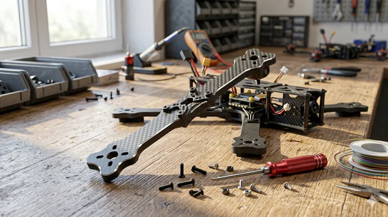
Carbon Fiber Drone Arm
Precision-molded carbon fiber drone arm combining unidirectional fiber for stiffness and woven layers for torsional strength. Designed for FPV, photography, and industrial drone platforms. Each arm is CNC-machined to exact specifications.