
A wind turbine blade tip travels at 80-110 meters per second, fast enough that a single 2-millimeter raindrop strikes the leading edge with the energy of a concentrated water jet. Over years of operation, billions of such impacts erode the protective coating, then the underlying composi
Introduction
A wind turbine blade tip travels at 80-110 meters per second, fast enough that a single 2-millimeter raindrop strikes the leading edge with the energy of a concentrated water jet. Over years of operation, billions of such impacts erode the protective coating, then the underlying composite, reducing aerodynamic performance and exposing the blade structure to moisture ingress. Rain erosion is therefore not a cosmetic issue: it is a maintenance cost, a performance loss, and a structural risk that must be designed out through material selection and qualified through controlled testing. This article explains how rain erosion testing works, compares the whirling arm and impact jet methods, and shows how test data translate into coating qualification decisions.
The Physics of Rain Erosion
Rain erosion is a liquid impingement phenomenon, distinct from solid particle erosion. When a droplet strikes a surface moving at high speed, a high-pressure region forms under the droplet edge, producing a lateral jet that impinges on the surface at several times the impact velocity. Repeated impacts generate stress waves that initiate micro-cracks in the coating; the cracks grow, pits form, and material loss accelerates. Three parameters dominate the damage rate:
- Impact velocity: Erosion rate scales with impact velocity raised to a power between 5 and 8, depending on material. A 20% increase in tip speed can multiply erosion by roughly two to four times, which is why faster offshore turbines demand better leading edge protection.
- Rainfall and droplet size: Damage accumulates with water loading, and larger droplets produce higher local pressures; artificial rain in tests uses droplet diameters of 1-3 millimeters to match real rainfall.
- Incubation time: Coatings resist erosion for a period of accumulated impact before measurable mass loss begins. Thicker protective coatings extend this incubation phase dramatically, which is why leading edge protection tape and thick paint systems outperform thin films.
These three parameters define what a test must control, and they are the reason field experience alone cannot qualify a coating system: no two sites, seasons, or turbines experience identical rain exposure.
Whirling Arm Testing: The Industry Workhorse
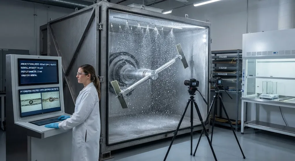
The whirling arm rig is the established method for coating qualification, codified in ASTM G73, the standard practice for liquid impingement erosion testing. Specimens are mounted at the ends of an arm that rotates inside a chamber while artificial rain is sprayed into the rotor plane. Specimens experience impacts at the rotation speed, typically 100-250 meters per second, covering the tip-speed range of wind turbines, radomes, and propeller blades. Tests run for hours or days, with specimens removed periodically for mass measurement, pit counting, and imaging. The key controlled variables are impact velocity, rainfall intensity, droplet diameter, test duration, and angle of incidence, normally set perpendicular to the specimen for leading edge simulations.
Because the arm rotates, each specimen sweeps through the rainfall continuously, reproducing the repeated-impact loading of a real blade surface. Results are reported as incubation time, erosion rate (mass loss per unit water volume), and damage threshold velocity — the velocity below which erosion is negligible. These outputs map directly onto qualification criteria: a coating qualified for an 80-meter-per-second blade may be disqualified at 110 meters per second, where the fifth-to-eighth-power scaling makes the erosion rate several times higher.
Impact Jet Methods and Alternatives
Whirling arm testing is slow and expensive, so researchers and coating developers use faster screening methods before committing to full qualification runs. The principal methods are compared below:
| Method | Representative standard | Typical impact velocity (m/s) | Droplet control | Throughput and cost | Typical use |
|---|---|---|---|---|---|
| Whirling arm | ASTM G73 | 100-250 | Artificial rain, 1-3 mm drops | Medium; several specimens per run | Qualification and acceptance testing |
| Single impact jet (SIJ) | Laboratory protocol | Up to 200 | Single droplet stream, precise | Low; high precision | Incubation studies, damage mechanisms |
| Multiple impact jet (MIJ) | Laboratory protocol | 150-200 | Repeated jet impacts | High; fast screening | Coating comparison and development |
| Erosion tunnel | Research facility | Varies by section | Controlled spray in airflow | Low; research scale | Flow-field and droplet-tracking studies |
| Field exposure | None standardized | Actual blade tip speed | Natural rainfall | Slowest; definitive | Validation of laboratory predictions |
Impact jet rigs fire a controlled stream of droplets at a stationary specimen, giving precise control over impact energy and allowing optical observation of the first damage. Their limitation is that they reproduce isolated impacts rather than the continuous, distributed rain loading of the whirling arm, so results are screening data rather than qualification evidence. Field exposure remains the final arbiter, but its multi-year duration makes it impractical as a primary qualification tool.
From Test Data to Qualification
Qualifying a leading edge protection system is a structured process that turns test data into a service-life statement. The typical workflow runs as follows:
- Define the target environment: The blade or component's tip speed, rainfall climate, and design life fix the test velocity, droplet size, and target water loading.
- Screen candidate systems: Fast methods such as MIJ compare coating candidates and down-select to two or three systems before expensive whirling arm runs.
- Qualify with the whirling arm: Selected systems are tested per ASTM G73 at the design tip speed, plus a margin velocity, with enough specimens and duration to establish incubation time and erosion rate statistically.
- Extrapolate to service life: Erosion data are converted into an expected service life using site-specific rainfall statistics, with the velocity scaling law applied to the blade's actual speed distribution.
- Verify in production: First articles and production batches are re-tested at reduced scope, and field returns are tracked to close the loop between laboratory prediction and real-world performance.
Industry guidance, including DNV-ST-0376 for wind turbine rotor blades, treats leading edge protection as a design-relevant element that must be justified by documented testing. In practice, coating suppliers publish erosion data generated on standardized rigs, and blade manufacturers perform their own confirmation runs before approving a system for series production.
Frequently Asked Questions
What is the difference between the whirling arm and single impact jet methods?
The whirling arm rig rotates specimens through artificial rainfall, reproducing the continuous, distributed, repeated impacts a real blade surface experiences; it is the method codified in ASTM G73 and is the standard evidence base for coating qualification. The single impact jet (SIJ) fires a controlled stream of droplets at a stationary specimen, giving precise control of impact energy and high-speed observation of the first damage. SIJ is a research and screening tool: it isolates individual impacts to study incubation and damage mechanisms, but it does not reproduce the statistical rain loading of service, so its results are used to compare candidates and design experiments, not as qualification evidence on their own. Multiple impact jet methods sit between the two, offering faster screening than the whirling arm with more realistic loading than a single jet.
Why does erosion rate scale so steeply with impact velocity?
Erosion rate scales with impact velocity raised to a power between 5 and 8, meaning a modest speed increase produces a dramatic rise in damage. The physical reason is that droplet impact pressure and the lateral jet velocity both scale with impact velocity, and the stress waves they generate drive crack nucleation and growth in a nonlinear way: beyond a threshold velocity, damage transitions from incubation to rapid material loss. For a wind turbine blade, this means a turbine with an 110-meter-per-second tip speed erodes several times faster than an identical blade at 90 meters per second, which is why faster offshore machines require thicker leading edge protection and why test qualification must be performed at the actual design tip speed plus a safety margin.
How is a coating system qualified for a specific blade design?
A coating system is qualified by testing at the blade's design tip speed plus a margin, typically using the whirling arm method per ASTM G73, with the test parameters matched to the site's rainfall climate: droplet diameter of 1-3 millimeters, target water loading, and impact angle normal to the leading edge. The test must produce statistically meaningful incubation time and erosion rate data, usually from multiple specimens run to defined water-loading levels. The data are then extrapolated to service life using site rainfall statistics and the velocity scaling law applied to the blade's actual speed distribution. The blade manufacturer reviews the results against its own criteria, often with confirmation runs, before approving the system; industry standards such as DNV-ST-0376 require this documented justification as part of the blade design basis.
Conclusion
Rain erosion testing exists because leading edge damage is expensive, invisible until it is advanced, and entirely governed by impact conditions that must be reproduced in the laboratory. The whirling arm rig per ASTM G73 remains the qualification workhorse, covering the 100-250 meter-per-second range that spans wind turbines, radomes, and propellers; impact jet methods accelerate screening and mechanism studies; and field exposure closes the validation loop. For any manufacturer selecting a leading edge protection system, the disciplined path is the same: define the environment, screen with fast methods, qualify with the whirling arm at design speed plus margin, and extrapolate honestly to service life.
YongXian supplies carbon fiber laminates, fabrics, and composite materials for blade, marine, and aerospace structures worldwide. Explore our carbon fiber product range for structural and leading edge applications, or contact our engineering team to discuss material specifications and qualification support for your program.
Related Articles
- Pultruded Carbon Fibre Rods: Cross-Sectional Properties and Standard Sizes
- Carbon Fiber Tube Fittings and Connectors: Joining Solutions for Structural Assemblies
- Carbon Fiber Plate Insert: Threaded Insert Design for Composite Structures
- Filament Wound Epoxy Tubing: Selection Guide for Industrial and Aerospace Applications
- Filament Wound Epoxy Tubes Advantages: Over Metal and Pultruded Alternatives
- Carbon Fiber Tube Strength: Analysis Methods and Design Allowables
Interested in Our Products?
Contact our team for competitive pricing and technical specifications.
Get a QuoteRelated Products

Carbon Fiber Fishing Rod Blank
High-quality carbon fiber fishing rod blank manufactured from multiple grades of Toray carbon fiber cloth. Available in a wide range of lengths, powers, and actions for freshwater and saltwater applications. Suitable for OEM rod building.

Carbon Fiber Plate — 3K Twill T700 1.5mm
Thin 1.5mm carbon fiber plate with 3K twill weave surface. Lightweight and stiff, commonly used for covers, panels, drone bodies, and applications requiring a premium aesthetic appearance.

Custom Carbon Fiber Medical Device Components
Medical-grade carbon fiber components manufactured for imaging equipment, surgical instruments, and patient support systems. Carbon fiber's radiolucency (X-ray transparency) and high strength-to-weight ratio make it ideal for CT scanner beds, wheelchair frames, surgical robot arms, and MRI-compatible accessories. Biocompatible resin systems available.

Square Carbon Fiber Tube — 3K Twill T700
Square cross-section carbon fiber tube manufactured with 3K twill weave for torsional strength. Preferred for structural frames, trusses, and support columns where rectangular geometry offers design flexibility.
Carbon Fiber Drone Arm
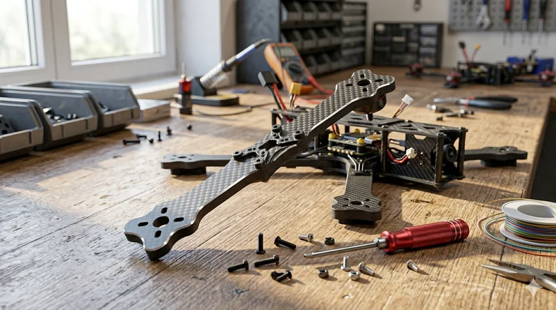
Precision-molded carbon fiber drone arm combining unidirectional fiber for stiffness and woven layers for torsional strength. Designed for FPV, photography, and industrial drone platforms. Each arm is CNC-machined to exact specifications.