
Wind turbine blades have grown to lengths that were unthinkable two decades ago, and that growth has pushed blade designers toward stiffer, lighter structural members. The spar cap — the long beam that runs from root to tip along each side of the blade and carries the majority of bendin
Introduction
Wind turbine blades have grown to lengths that were unthinkable two decades ago, and that growth has pushed blade designers toward stiffer, lighter structural members. The spar cap — the long beam that runs from root to tip along each side of the blade and carries the majority of bending load — is the single most structurally critical component in the blade. For blades above roughly 70 meters, pultruded carbon spar caps have displaced infused glass laminates as the preferred solution because carbon fiber provides roughly three times the modulus of glass at less than half the density, allowing a longer, lighter blade without a proportional increase in gravitational loads. This article is written for procurement engineers, quality managers, and blade manufacturers who need to specify, audit, and accept pultruded carbon spar caps in series production.
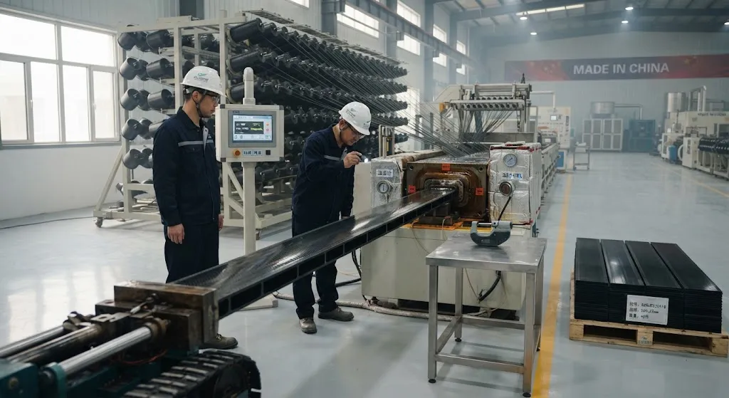
The challenge with pultrusion is consistency. A pultrusion line is continuous: fiber creels feed resin-impregnated tow through a heated die at speeds of 0.3 to 1.5 meters per minute, and the profile emerges fully cured. That continuous nature delivers excellent economics, but it also means that a single shift of unstable process conditions can produce hundreds of meters of a spar cap with detectable but borderline quality. The quality system around a pultruded spar cap supply therefore matters as much as the fiber itself. This article walks through the parameters that define a good spar cap, the tests that verify them, and the production-control philosophy that separates a reliable supplier from a commodity one.
Why Pultruded Carbon Spar Caps Took Over Blade Design
Spar cap manufacturing has two dominant routes, and the choice has real structural consequences:
| Property | Pultruded carbon spar cap | Infused carbon/glass spar cap |
|---|---|---|
| Fiber volume fraction | 60-68% (die-controlled) | 52-58% (infusion variability) |
| Typical laminate modulus (GPa) | 150-170 (carbon UD) | 100-140 (carbon content dependent) |
| Void content | Below 1% when process is stable | 1-3%, strongly operator dependent |
| Thickness tolerance | ±0.1-0.2 mm per profile | ±0.5-1 mm, skill dependent |
| Production rate | Continuous, 0.3-1.5 m/min | Batch, mold cycle limited |
| Blade integration | Bonded or bolted plates | Co-cured or infused in situ |
The fiber volume fraction column explains most of the structural difference. Because the pultrusion die squeezes excess resin out at a fixed cross-section, the fiber content is set by the number of tows fed into the die rather than by operator pouring technique. The result is a laminate with a high, repeatable fiber content and very low voids — exactly the two properties that govern compressive strength and fatigue life in a load-bearing compression member. Blades above roughly 80 meters now routinely combine a pultruded carbon cap with glass shear webs and skins, using the carbon cap where bending stiffness matters most.
The Critical Quality Parameters
Five parameters dominate the quality conversation for pultruded carbon spar caps. Each one has a direct structural consequence:
- Fiber volume fraction (FVF): Measured by resin burn-off or acid digestion per ASTM D3171. FVF below specification reduces modulus and compressive strength; FVF too high starves the fiber of resin and creates dry spots that fail in compression early.
- Void content: Determined by resin density comparison per ASTM D2734 or by micrographic analysis. Voids nucleate microcracks under fatigue loading, and void content above 1-2% measurably reduces interlaminar shear strength and fatigue life.
- Straightness and twist: A pultruded plate that exits the die with bow or twist will not bond flat into the blade mold, creating stress concentrations at the bond line. Suppliers verify this with straight-edge and flatness gauges at every lot.
- Cross-section geometry: Width and thickness deviations shift the neutral axis of the cap and complicate butt-joint splicing of adjacent plates. Modern blades use dozens of plates per cap, so dimensional consistency is a production problem, not just a tolerance problem.
- Interlaminar shear strength (ILSS): Measured by short-beam shear per ASTM D2344. ILSS is the property most sensitive to poor fiber-matrix adhesion and voids, and it is the single best early-warning test for process drift.
Experienced quality teams treat these five as a correlated package rather than as independent checks. A sudden change in ILSS across a lot almost always traces back to a resin-bath temperature drift or a creel tension change that also nudges FVF — which is why trend monitoring beats single-lot pass/fail decisions.
Lot Control and Traceability
A wind blade spar cap is assembled from many individual pultruded plates, typically 30 to 80 plates per cap depending on blade size and plate dimensions. Plates arrive in production lots defined by resin batch, fiber creel set, and die run. Traceability requirements are therefore specific: each plate should carry a lot identifier that ties it to raw material certificates, the pultrusion line, the time window of production, and the full set of release tests. Leading suppliers retain a sample from each lot for archive, so that a blade-level failure found three years later can be traced back to an exact production window and re-tested. This level of discipline is what separates aerospace-grade supply habits from commodity material handling, and it is now expected by major turbine OEMs in their supplier audits.
Testing and Acceptance Criteria
Release testing for a spar cap lot follows a standard package that maps directly onto the properties the blade analysis needs:
| Test | Standard | Typical acceptance criterion |
|---|---|---|
| Fiber volume fraction | ASTM D3171 | 60-68% within target window |
| Void content | ASTM D2734 | Below 1.5% |
| Interlaminar shear strength | ASTM D2344 | ≥ 0.9 times the qualified baseline |
| Tensile modulus and strength | ASTM D3039 | ≥ 95% of certified value |
| Compressive strength | ASTM D6641 | ≥ 95% of certified value |
| Glass transition temperature | ASTM D7028 (DMA) | ≥ 10 °C above cure temperature |
| Ultrasonic C-scan or porosity line check | Internal or ASTM E317 | No porosity clusters above reject threshold |
Two practical notes on acceptance testing. First, the baseline values in the table must come from the qualified material system used in the blade design allowables — a generic datasheet number is not a substitute for the qualified baseline, because resin chemistry differences change the acceptable windows. Second, destructive mechanical tests sample only a fraction of the lot, so the quality system must pair them with non-destructive checks that cover every meter: ultrasonic porosity scanning, laser profilometry for geometry, and visual inspection for surface defects such as resin starvation or die drag marks.
Statistical Process Control in Series Production
Because pultrusion is continuous, the most powerful quality tool is trend data rather than end-of-line testing. Suppliers that run effective series production maintain control charts on the parameters that drive structural performance:
- FVF and density pulled from every shift: a drifting mean is caught within hours, not at the end of the lot.
- Die temperature and line speed logged continuously: these two inputs control cure state, and either one leaving its window shows up first in the process data, before it shows up in the parts.
- Process capability indices (Cp and Cpk): computed on thickness, width, and straightness. A Cpk below 1.33 signals that the process cannot hold tolerance reliably, even if the current lot passes.
- ILSS trend charts across lots: a slow downward drift is an early indicator of resin batch drift or fiber sizing incompatibility long before parts fail specification.
For buyers, the practical question is not whether the supplier runs SPC, but whether the SPC data is actually linked to release decisions. A supplier that can show control charts with their release tests, and that holds or quarantines lots when charts drift, is managing risk; a supplier that only provides certificates of conformance is transferring that risk to the blade manufacturer.
Common Defects and Root Causes
Knowing what can go wrong helps both sides of the contract speak the same language during audits and non-conformance discussions:
- Dry fiber clusters: caused by creel tension imbalance or a blocked resin bath; visible as lustrous dry spots on the profile surface and detectable as low FVF.
- Surface cracks or crazing: typically from excessive pulling resistance or premature cure in the die, indicating a temperature or speed misalignment.
- Twist and bow: usually from asymmetric fiber distribution or uneven die heat, often caught by a straightness gauge at the puller.
- Porosity spikes: traced to resin viscosity change, moisture pick-up in the resin, or a worn die land creating a pressure drop.
- Incomplete cure: shows up as depressed glass transition temperature at the core of thick profiles; verified by DMA on cross-section samples.
Frequently Asked Questions
What fiber volume fraction should I specify for a pultruded carbon spar cap?
For a wind blade spar cap, specify an FVF of 60-68% measured by resin burn-off or acid digestion per ASTM D3171. This range is achievable in well-run pultrusion, gives a repeatable axial modulus of roughly 150-170 GPa with standard-modulus carbon, and leaves enough resin to wet the fiber fully and keep void content below about 1%. The exact target should come from the qualified material system used in the blade allowables, because the resin chemistry influences what FVF is optimal.
Why is void content so important for spar cap fatigue life?
Voids act as crack-initiation sites under cyclic compression and shear loading. A void nucleates a microcrack, the microcrack grows under repeated loading, and in a thick compression member this can lead to premature delamination and a reduction in fatigue life that is disproportionate to the small void volume. Industry practice keeps void content below roughly 1% for critical spar cap material, because the fatigue penalty of moving from below 1% to above 2% is far larger than the density penalty suggests.
How should I audit a pultruded spar cap supplier?
Ask for three things in the audit. First, the process window documentation: die temperature, line speed, and resin bath conditions, with evidence that the window is monitored continuously. Second, the linkage between SPC data and release decisions: request the last year of FVF, void, and ILSS control charts next to the certificate of conformance. Third, traceability: trace one specific plate back to its resin batch, fiber creel, and production time window, and confirm archive samples are retained. If any of the three is missing, the supplier is managing certificates rather than risk.
Conclusion
Pultruded carbon spar caps earn their place in modern wind blade design through a combination of high fiber volume fraction, low void content, and continuous production economics. But those advantages only survive contact with the production floor if the quality system is built around them: tight control of the five critical parameters, lot-level traceability back to raw materials, a release testing package that matches the blade allowables, and statistical process control that catches drift before it becomes a non-conformance. For the buyer, the difference between a reliable spar cap supply and a risky one shows up in the control charts and the traceability records, not in the certificate of conformance.
If you are developing or qualifying pultruded carbon profiles for wind energy or other structural applications, review our carbon fiber product range or contact our engineering team to discuss fiber selection, standard modulus versus intermediate modulus grades, and the specifications your spar cap program should carry.
Part of topic
Related Articles
- Bio-Based Carbon Fiber Precursors: Lignin and Polyethylene for Low-Cost Production
- Large-Tow Carbon Fiber Cost Analysis: 48K vs 60K Price-Performance Comparison
- Carbon Fiber-Resin Interface Bonding: Surface Treatment and Coupling Agent Optimization
- Digital Twin for Carbon Fiber Manufacturing: Real-Time Process Monitoring and Defect Prevention
- Thermoplastic Carbon Fiber Welding for Automotive: Ultrasonic and Induction Welding Process Windows
- Large-Tow Carbon Fiber Wet Spinning: Process Optimization for 48K/60K Production Efficiency
Interested in Our Products?
Contact our team for competitive pricing and technical specifications.
Get a QuoteRelated Products

Carbon Fiber Fishing Rod Blank
High-quality carbon fiber fishing rod blank manufactured from multiple grades of Toray carbon fiber cloth. Available in a wide range of lengths, powers, and actions for freshwater and saltwater applications. Suitable for OEM rod building.

Carbon Fiber Plate — 3K Twill T700 3.0mm
Medium-thickness 3.0mm carbon fiber plate offering significantly higher load capacity while maintaining attractive 3K twill finish. Suitable for structural brackets, reinforcement plates, and load-bearing panels.

Carbon Fiber Plate — 3K Twill T700 1.5mm
Thin 1.5mm carbon fiber plate with 3K twill weave surface. Lightweight and stiff, commonly used for covers, panels, drone bodies, and applications requiring a premium aesthetic appearance.

Square Carbon Fiber Tube — 3K Twill T700
Square cross-section carbon fiber tube manufactured with 3K twill weave for torsional strength. Preferred for structural frames, trusses, and support columns where rectangular geometry offers design flexibility.
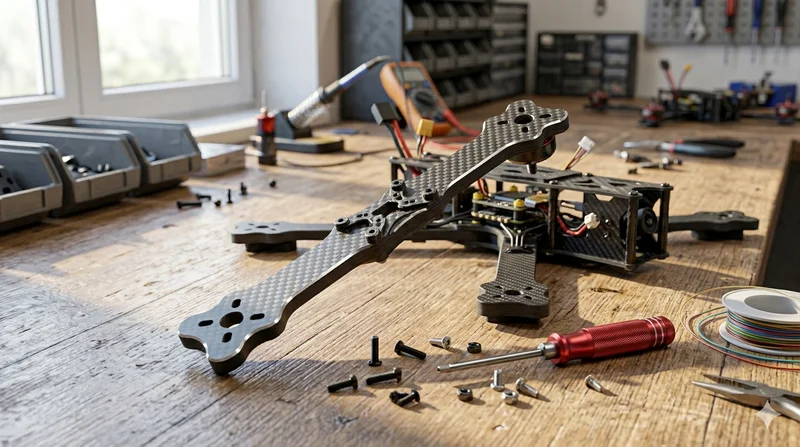
Carbon Fiber Drone Arm
Precision-molded carbon fiber drone arm combining unidirectional fiber for stiffness and woven layers for torsional strength. Designed for FPV, photography, and industrial drone platforms. Each arm is CNC-machined to exact specifications.