
Blade architecture has been remarkably stable for two decades. A blade is a laminated shell, a spar cap that carries the bending load, and a web or shear web system that keeps the cap in position; the spar cap is almost always built at the blade factory, either by stacking pultruded pla
Introduction
Blade architecture has been remarkably stable for two decades. A blade is a laminated shell, a spar cap that carries the bending load, and a web or shear web system that keeps the cap in position; the spar cap is almost always built at the blade factory, either by stacking pultruded plates in a mold or by automated fiber placement. This works, but it ties the entire blade to the largest and slowest step in the factory — the full-length spar cap layup and its curing cycle — and it produces a structure that can only be transported as one oversized piece.
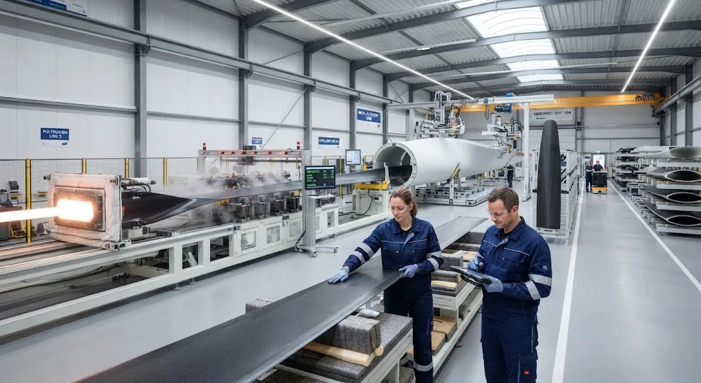
A different route is now being demonstrated under the RECREATE program. Instead of assembling a spar cap inside the blade mold, the blade is built around a continuous pultruded spar produced as an endless profile, to which modular shell segments are attached by adhesive bonding or detachable joints. The leading edge can be manufactured as a separate thermoformed organic-sheet component rather than laminated into the shell. The result is a blade whose structural components are made on continuous process lines, whose joints are designed for assembly and disassembly, and whose factory layout more closely resembles modular manufacturing than the traditional closed-mold blade hall.
Continuous versus Segmented Spar Architecture
The difference between the two approaches is best expressed in the load path. A segmented spar cap is a series of plate stacks bonded end-to-end along the blade; each stack-to-stack butt joint carries the axial load across an adhesive or cured-resin interface, and the joints are the first candidate location for fatigue damage. A continuous pultruded spar is a single endless laminate produced in one process, so the load path runs through one piece along the entire blade length without a single splice. The table below contrasts the two architectures:
| Parameter | Segmented Spar Cap (Mold-Built) | Continuous Pultruded Spar |
|---|---|---|
| Load path | Broken by butt joints between stacks | Continuous, no splices along length |
| Production process | Hand stacking or AFP in blade mold | Endless pultrusion line, cut to length |
| Joint risk | Stack-to-stack adhesive joints | Only the modular shell joints |
| Transport | Full blade as one oversize piece | Blade sections ship separately |
| Repair | In-situ cap repair inside the mold | Sectional replacement at modular joints |
| Factory floor | Full-length mold dominates layout | Continuous lines + assembly stations |
Removing the butt joints concentrates the design risk in the modular joints that attach shells and sections to the spar — but it converts a fixed, mold-bound structure into one that can be disassembled, and that conversion pays for itself across transport, repair and service life.
Pultrusion as the Continuous Manufacturing Route
Pultrusion is the natural process for a continuous spar because it produces an endless, constant-cross-section laminate at industrial speed. Wide carbon or glass fiber reinforcement, typically stitched fabrics or mixed UD/glass architectures, is pulled through a resin bath and a heated die, emerging as a cured profile whose fiber volume fraction and dimensions are set by the die and the line. For a spar, the process contributes three properties that segmented construction cannot match. First, rate: a pultrusion line advances meters per minute, so a 100-meter spar equivalent is produced in fractions of an hour of line time, compared with days of mold occupancy for a laminated cap. Second, consistency: because the profile is drawn continuously through the same die, every meter sees the same fiber architecture, resin content and cure — cross-sectional properties repeat along the entire length without the variability of hand-stacked batches. Third, length economics: the die produces an endless profile, so cutting to blade length is a simple trimming step, and offcuts are short, predictable and reusable in other blade or product programs.
The spar profile itself can be shaped for bonding: a box or trapezoid section with flat bonding flanges gives the modular shell joints a defined surface to mate against.
Design-for-Manufacturing Rules for Modular Blades
Continuous-spar blades move the manufacturing complexity from the mold floor to the joint line. Six rules govern the design:
- Bonding surfaces first: every shell-to-spar and section-to-section joint is designed with flat, accessible bonding flanges before any other detail, so adhesive application and pressure can be automated.
- Controlled gap tolerance: joint gaps are specified in tenths of a millimeter and held by the pultrusion die and machined edges, keeping bond-line thickness uniform across the joint.
- Thermal forming for leading edges: the leading edge is formed from organic sheet in a thermoforming step, producing a dimensionally accurate profile that bonds consistently to the shell rather than relying on hand-laminated geometry.
- Joint access: every joint must be reachable for inspection and, where specified, for disassembly — the tooling layout plans for release and re-clamping, not just assembly.
- Component standardization: shell segments, leading edge profiles and joint hardware are standardized across blade sizes, so one process line serves several models and inventory is shared.
- Adhesive cure as logistics, not cycle time: curable adhesives are chosen so that joint cure can proceed offline while the line continues, decoupling assembly rate from adhesive cycle time.
These rules are the difference between a concept drawing and a factory plan: they turn the modular blade from a structural idea into a process with measurable throughput.
Detachable Modular Joints and Sectional Logistics
The same modular joints that make assembly automated make the blade divisible for its entire life cycle. Three consequences matter commercially:
- Transport: a 100-meter blade shipped as one piece dominates road, rail and port logistics; a modular blade ships as spar, shells and leading edge in standard containers, opening up factories and sites that oversized transport cannot reach and cutting the cost and lead time of year-round logistics.
- Repair: a damaged shell segment or leading edge section is replaced at its joint instead of repairing a bonded monolith in the field — the repair becomes a planned exchange that can be done at a service facility rather than an on-site patch.
- Upgrade and end-of-life: sections can be swapped for improved designs, and at decommissioning the blade can be dismantled into materials that separate cleanly, supporting the component-level recycling that European waste regulations increasingly expect.
The detachable feature is not a compromise on strength; it is a deliberate design choice that trades a small amount of joint complexity for a large improvement in logistics and serviceability.
The RECREATE Demonstration
The RECREATE program puts these principles into practice at industrial scale. Its demonstration blade combines three elements that together define the modular route: a pultruded continuous spar produced as an endless profile, modular shells attached by adhesive bonding engineered for automated assembly, and a leading edge manufactured as a thermoformed organic-sheet component rather than laminated into the shell. The program's stated goal is to re-localize blade manufacturing in Europe — to prove that a factory in a high-wage region can produce blades competitively by replacing mold-bound, labor-intensive construction with continuous process lines and standardized modular assembly. The organic-sheet leading edge, in particular, replaces intricate hand lamination along the most curvature-critical part of the blade with a formed component that repeats identically on every blade.
The demonstration therefore operates on two levels. As engineering, it validates the continuous spar load path, the adhesive joint design and the thermoforming process on a real blade geometry. As economics, it tests whether a European blade plant running continuous lines and modular assembly can match the price points of incumbents — the same question the thermoplastic automation programs are asking, but answered with pultruded thermoset spar technology and standardized joints.
Certification and Testing Considerations
Modular construction changes what the certification evidence must prove. The continuous spar itself is straightforward to qualify: pultruded profiles have a long certification history in blades and other structures, and the continuous load path removes the butt-joint fatigue cases that segmented designs must demonstrate. The new evidence burden concentrates in the joints:
- Adhesive joint allowables: lap-shear and peel data across the full service temperature and humidity range, with safety factors applied to the bond-line thickness tolerance.
- Joint fatigue spectrum: cycle testing of representative shell-to-spar joints under the blade's bending spectrum, including the gap-tolerance extremes that occur in production.
- Non-destructive inspection: reliable inspection of adhesive joints — ultrasonic and thermographic methods adapted to the specific joint geometry, with acceptance criteria that distinguish disbonds from acceptable porosity.
- Disassembly demonstration: if detachable joints are load-bearing, proof that re-assembled joints meet the original allowables after a specified number of assembly cycles.
None of this is exotic; it is the standard toolset of bonded composite structures, transferred to a blade whose joints are engineered as first-class production details.
Frequently Asked Questions
Why is a continuous pultruded spar better than a segmented spar cap?
With a segmented design, the spar cap is built from plate stacks joined end-to-end inside the blade mold, so the axial load must cross adhesive butt joints between stacks — the natural first location for fatigue damage to develop. A continuous pultruded spar, by contrast, is a single infinite laminate produced on one pultrusion line, so the load path runs through one piece without any splices. The continuous route also produces its cross-section at meters per minute with consistent fiber architecture along the full length, while a mold-built cap occupies the mold for days of layup and cure. The trade-off is that the shell-to-spar joints need careful design, but that design effort buys a divisible structure that is easier to transport, repair and recycle.
How do detachable modular joints affect blade strength and safety?
Detachable modular joints are designed as load-bearing details, not convenience fittings. The joint surfaces are flat bonding flanges with controlled gap tolerance, the adhesive allowables are established across the service temperature range, and the joints are fatigue-tested under the blade bending spectrum with the same safety factors applied to other bonded structure. Certification then requires demonstrating that re-assembled joints meet the original allowables. The strength of the joints is an engineered property; the modular format is a separate feature that pays back through transport flexibility, replacement repair and end-of-life dismantling.
What is the RECREATE demonstration trying to prove?
RECREATE is demonstrating a modular blade route: a pultruded continuous spar, adhesively bonded modular shells and a thermoformed organic-sheet leading edge. Its engineering goal is to validate the load path, joint design and forming process on a real blade geometry; its economic goal is to prove that a European factory running continuous lines and modular assembly can match incumbent price points, re-localizing blade production in high-wage regions. It is thus both a structural test and a cost model, with the joints as the pivot between the two.
Conclusion
The continuous pultruded spar is a design decision with manufacturing consequences: it removes the spliced load path and the mold-bound layup of the segmented cap, substitutes an endless profile produced at meters per minute, and turns the blade into a modular assembly whose joints are engineered for bonding, inspection and disassembly. The RECREATE demonstration combines that spar with a thermoformed organic-sheet leading edge and modular adhesive assembly to support European re-localization of blade manufacturing, mirroring the automation push of thermoplastic programs. For blade programs, the practical question is no longer whether modular assembly is possible, but which production mix of pultrusion, bonding and modular joints wins on cost at their scale.
For engineers specifying spars and bonding-friendly reinforcement for modular blade programs, review our pultruded plate and carbon fiber reinforcement range, or contact our engineering team to discuss spar profiles, joint-friendly fabrics and qualification support for your next blade architecture.
Part of topic
Related Articles
- Bio-Based Carbon Fiber Precursors: Lignin and Polyethylene for Low-Cost Production
- Large-Tow Carbon Fiber Cost Analysis: 48K vs 60K Price-Performance Comparison
- Carbon Fiber-Resin Interface Bonding: Surface Treatment and Coupling Agent Optimization
- Digital Twin for Carbon Fiber Manufacturing: Real-Time Process Monitoring and Defect Prevention
- Thermoplastic Carbon Fiber Welding for Automotive: Ultrasonic and Induction Welding Process Windows
- Large-Tow Carbon Fiber Wet Spinning: Process Optimization for 48K/60K Production Efficiency
Interested in Our Products?
Contact our team for competitive pricing and technical specifications.
Get a QuoteRelated Products

Carbon Fiber Fishing Rod Blank
High-quality carbon fiber fishing rod blank manufactured from multiple grades of Toray carbon fiber cloth. Available in a wide range of lengths, powers, and actions for freshwater and saltwater applications. Suitable for OEM rod building.

Carbon Fiber Plate — 3K Twill T700 1.5mm
Thin 1.5mm carbon fiber plate with 3K twill weave surface. Lightweight and stiff, commonly used for covers, panels, drone bodies, and applications requiring a premium aesthetic appearance.

Square Carbon Fiber Tube — 3K Twill T700
Square cross-section carbon fiber tube manufactured with 3K twill weave for torsional strength. Preferred for structural frames, trusses, and support columns where rectangular geometry offers design flexibility.
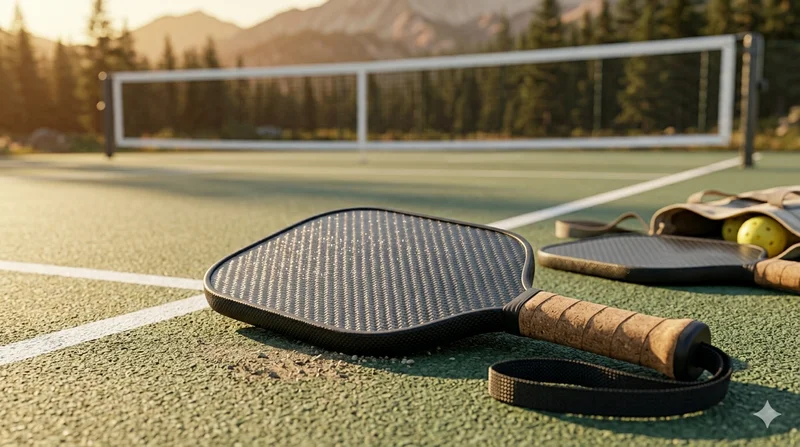
Carbon Fiber Pickleball Paddle
High-performance pickleball paddle with Toray T700 carbon fiber face and polypropylene honeycomb core. Delivers excellent power-to-weight ratio, spin generation, and vibration dampening for competitive play.

Carbon Fiber Plate — UD Unidirectional T700
Unidirectional carbon fiber plate with all fibers oriented in a single direction for maximum strength along the fiber axis. Essential for structural reinforcements, splints, and applications where load direction is predictable.