
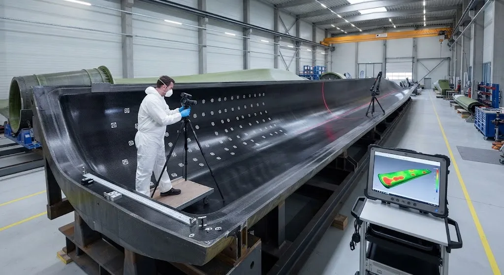
A wind turbine blade is 80 meters long, cured in a mold that must hold its own geometry to within a few millimeters over its entire surface, and inspected against a digital model that expects sub-millimeter precision at the spar cap and trailing edge. A coordinate measuring machine cann
Introduction
A wind turbine blade is 80 meters long, cured in a mold that must hold its own geometry to within a few millimeters over its entire surface, and inspected against a digital model that expects sub-millimeter precision at the spar cap and trailing edge. A coordinate measuring machine cannot do this job: its working volume is a few cubic meters, and a blade is a hundred times larger. The technologies that fill this gap are photogrammetry and laser scanning, two non-contact methods that turn a camera or a scanner into a full-surface measuring instrument. Together they have become the standard approach for large composite part QC in molding, production and in-service inspection.
This article explains how both technologies work, where they fit in the tooling and blade QC workflow, and how their data compares with traditional coordinate metrology.
How Photogrammetry Works
Photogrammetry measures 3D coordinates from 2D photographs. Targets are applied to the part or tooling, the object is photographed from many angles with a calibrated high-resolution camera, and software triangulates the target positions from the parallax between images. The technique has two distinct modes in composite practice:
- Coded-target photogrammetry: Self-identifying targets allow the software to automatically track thousands of points across overlapping images. This mode is used for large-scale measurements — mold reference points, blade stations, assembly alignment — where accuracy of 0.1 mm over tens of meters plus processing speed matter more than full-surface coverage.
- Projected-pattern photogrammetry (structured light): A projector and cameras combine to digitize dense surface point clouds, typically for tooling surfaces a few meters across. This mode approaches the density of laser scanning while preserving the portability and low hardware cost of a camera-based system.
Both modes deliver one crucial practical benefit on the factory floor: complete portability. A photogrammetry kit fits in a case, needs no temperature-controlled metrology lab, and can be used on a blade in a production hall or a mold inside the tooling shop.
Laser Scanning and Point-Cloud Deviation Analysis
Laser scanners sweep a laser line over the surface and record millions of points per scan, producing dense point clouds that describe the geometry as it actually is — not as a set of discrete target points, but as a continuous surface. Handheld scanners are ideal for mold cavities and localized features; long-range terrestrial scanners are used for the full envelope of an 80-meter blade.
The power of both technologies emerges in the analysis step. The acquired point cloud is registered to the CAD model and a deviation map is computed: every point on the measured surface is compared with the nominal surface, producing a color-coded error map. This is where large-part QC decisions are actually made:
| Inspection dimension | Traditional CMM | Point-cloud (photogrammetry / laser scanning) |
|---|---|---|
| Convenient working envelope | ~1-3 m per setup | Meters to 80+ m |
| Typical accuracy | 0.01-0.05 mm (contact) | 0.1-1 mm depending on system geometry |
| Surface coverage | Discrete point sampling | Full-surface continuous coverage |
| Measurement time for a full blade envelope | Impractical (days) | Hours with multiple stations |
| Data output | Point coordinates for GD&T features | Millions of points, deviation maps, GD&T features |
| Environment sensitivity | Requires stable, temperature-controlled conditions | Works in production halls and outdoors |
The deviation map converts raw geometry into an actionable story: a color band that shows exactly where the suction side drifts out of tolerance, how the twist distribution rides relative to nominal, and where the trailing edge thickness accumulates. That spatial story is the difference between "the blade is out of tolerance" and knowing precisely where, by how much, and in which direction to correct the mold.
Tooling QC: Closing the Loop on Mold Geometry
In composite manufacturing, the mold is the master. Blade molds and aerospace tooling are themselves composite structures — carbon fiber shells on steel or composite frames — that distort as they cure, after demolding and during service. Photogrammetry is the workhorse for tooling verification: reference targets bonded to the mold surface are re-measured on a scheduled basis, and the deviation from the as-built digital twin reveals creep, wear, or the effect of repeated cure cycles.
The practical rhythm of tooling inspection follows a simple but effective pattern. After manufacturing and before the first production cure, the mold receives a full baseline measurement that becomes the digital twin the mold was made to. During early production, re-measurement after every few cures tracks whether geometry is stable or drifting. Once the curve flattens, the interval can be extended to scheduled campaigns — quarterly tooling audits are typical for high-throughput blade molds. This baseline-and-trend approach means geometry problems are caught while they are still small corrections to the mold surface, not after hundreds of parts have accumulated the same defect.
Laser scanning adds the surface-level picture that targets miss — local denting, resin deposits, or distortion of the flange region. The two methods are routinely combined: photogrammetry establishes the global reference frame and large-scale geometry, while handheld scanning fills in dense detail where surface condition matters. Because tooling deviations transfer directly into part deviations, tooling QC is also the most leveraged inspection in the entire process: correcting the mold corrects every blade cured in it.
Blade QC: From Mold Validation to In-Service Survey
On finished blades, point-cloud inspection plays three distinct roles. During prototype validation, a full laser scan verifies that the blade matches the design envelope, capturing twist, chord and profile deviations that influence aero performance. In production, station-based photogrammetry checks key certification dimensions quickly without scanning every surface, protecting throughput. In service, terrestrial laser scanning documents blade condition and repairs, producing baseline geometry that follow-up inspections can compare against over years of operation.
One recurring lesson from blade programs is the importance of registering the point cloud to the design coordinate system correctly. An 80-meter blade can be geometrically perfect and still report large errors if the scan alignment is off by a fraction of a degree at the root. Practitioners anchor scans with photogrammetric targets at known stations, then use best-fit alignment with a controlled number of alignment points so that the deviation map reflects real manufacturing error rather than alignment error.
Frequently Asked Questions
Why not just use a traditional CMM for large composite parts?
Contact CMMs and laser trackers remain the most accurate instruments in metrology, but their working volume and environment requirements make full-surface measurement of meter-scale parts impractical. A CMM has a typical envelope of one to three meters and needs controlled temperature; a blade mold or blade spans tens of meters and lives in a production hall. Photogrammetry and laser scanning trade some absolute accuracy (roughly 0.1-1 mm versus 0.01-0.05 mm) for portability and complete surface coverage, which is the trade that large composite parts actually need.
What accuracy can photogrammetry realistically deliver on a factory floor?
With calibrated cameras, stable referencing and good target application, coded-target photogrammetry routinely delivers coordinate accuracy in the range of 0.05-0.2 mm over measurement fields of several meters, and proportionally larger over much larger fields. Structured-light systems offer higher point density on smaller surfaces. The practical accuracy on a production floor depends less on the technology class and more on the measurement plan: target placement, camera network geometry, temperature variation and registration strategy all dominate the final error budget.
How do I start using point-cloud QC for blade tooling without a major investment?
Start with photogrammetry: a calibrated camera, a target kit and analysis software are the lowest-cost entry point and cover the highest-value job — scheduled mold geometry verification. Build a target map on the mold, define the as-built digital twin with one complete measurement, and re-measure on a fixed schedule to build a trend baseline before problems appear. Add handheld laser scanning when you need dense surface detail for specific investigations such as flange flatness or local distortion. This staged approach delivers useful tooling QC from day one and grows into full-surface blade inspection as needed.
Conclusion
Photogrammetry and laser scanning have made full-surface geometry verification practical at the scale of wind turbine blades and composite tooling — the dimension where traditional contact metrology stops working. Photogrammetry establishes global geometry with sub-millimeter capability and complete portability; laser scanning adds dense point clouds and deviation maps that tell exactly where and how a surface drifts from nominal. Used together, they close the loop between tooling quality and part quality in a way that discrete point measurement never could.
YongXian supplies the carbon fiber materials used in blades and tooling, and our engineering team routinely supports thickness, flatness and geometric tolerance verification discussions with manufacturers. Explore our carbon fiber product range or contact our team to discuss material supply and QC considerations for your blade or tooling program.
Part of topic
Related Articles
- Bio-Based Carbon Fiber Precursors: Lignin and Polyethylene for Low-Cost Production
- Large-Tow Carbon Fiber Cost Analysis: 48K vs 60K Price-Performance Comparison
- Carbon Fiber-Resin Interface Bonding: Surface Treatment and Coupling Agent Optimization
- Digital Twin for Carbon Fiber Manufacturing: Real-Time Process Monitoring and Defect Prevention
- Thermoplastic Carbon Fiber Welding for Automotive: Ultrasonic and Induction Welding Process Windows
- Large-Tow Carbon Fiber Wet Spinning: Process Optimization for 48K/60K Production Efficiency
Interested in Our Products?
Contact our team for competitive pricing and technical specifications.
Get a QuoteRelated Products

Carbon Fiber Fishing Rod Blank
High-quality carbon fiber fishing rod blank manufactured from multiple grades of Toray carbon fiber cloth. Available in a wide range of lengths, powers, and actions for freshwater and saltwater applications. Suitable for OEM rod building.

Custom Carbon Fiber Medical Device Components
Medical-grade carbon fiber components manufactured for imaging equipment, surgical instruments, and patient support systems. Carbon fiber's radiolucency (X-ray transparency) and high strength-to-weight ratio make it ideal for CT scanner beds, wheelchair frames, surgical robot arms, and MRI-compatible accessories. Biocompatible resin systems available.

Carbon Fiber Plate — 3K Twill T700 1.5mm
Thin 1.5mm carbon fiber plate with 3K twill weave surface. Lightweight and stiff, commonly used for covers, panels, drone bodies, and applications requiring a premium aesthetic appearance.

Square Carbon Fiber Tube — 3K Twill T700
Square cross-section carbon fiber tube manufactured with 3K twill weave for torsional strength. Preferred for structural frames, trusses, and support columns where rectangular geometry offers design flexibility.
Carbon Fiber Drone Arm
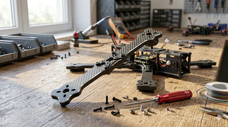
Precision-molded carbon fiber drone arm combining unidirectional fiber for stiffness and woven layers for torsional strength. Designed for FPV, photography, and industrial drone platforms. Each arm is CNC-machined to exact specifications.