
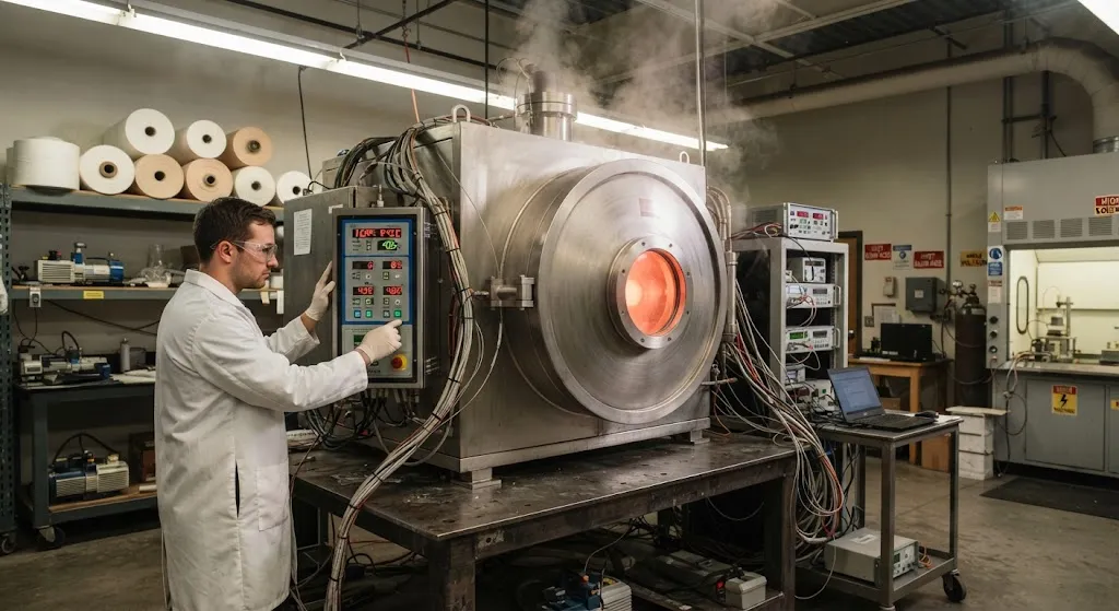
Carbon fiber production begins with the thermal conversion of polyacrylonitrile (PAN) precursor fiber into high-carbon-content material through a process called carbonization. In conventional production, this step requires heating the fiber to 1,000-1,500°C in nitrogen-atmosphere electric furnaces f
Introduction
Carbon fiber production begins with the thermal conversion of polyacrylonitrile (PAN) precursor fiber into high-carbon-content material through a process called carbonization. In conventional production, this step requires heating the fiber to 1,000-1,500°C in nitrogen-atmosphere electric furnaces for hours, consuming enormous amounts of electricity — typically 50-80 kWh per kilogram of carbon fiber produced. As global carbon fiber demand grows toward 200,000 tons per year, manufacturers face increasing pressure to reduce energy consumption per kilogram while maintaining or improving fiber quality.
Microwave-assisted carbonization offers a fundamentally different approach. Instead of relying on conductive and convective heat transfer from external heating elements, microwave energy penetrates the fiber bundle and generates heat directly through dielectric loss in the carbonizing material. This volumetric heating mechanism can reduce carbonization time by 50-80% and energy consumption by 30-60% compared to conventional electric furnaces. This article explains the physics behind microwave carbonization, the reactor designs that make it practical, and the quality advantages that are driving adoption in pilot and commercial production facilities worldwide.
Physics of Microwave Heating for Carbon Fiber
Microwave heating works on a principle fundamentally different from conventional thermal processing. When electromagnetic radiation at 2.45 GHz (the standard industrial frequency) interacts with a material, it deposits energy through two mechanisms: dipolar polarization and interfacial polarization. For PAN precursor during carbonization, the mechanism evolves through three distinct phases:
| Carbonization Stage | Temperature Range | Microwave Absorption Mechanism | Energy Coupling Efficiency |
|---|---|---|---|
| Stabilization | 200-300°C | Dipolar polarization of nitrile groups | Low (2-8%) |
| Carbonization | 300-800°C | Interfacial polarization in forming carbon structure | Rising (15-40%) |
| Graphitization | 800-1,500°C | Conductive loss in graphitic domains | High (40-70%) |
The critical insight is that carbon fiber becomes an excellent microwave absorber as it carbonizes. The developing graphitic structure has high dielectric loss, meaning it converts microwave energy to heat very efficiently. This creates a self-regulating process: areas that are further along in carbonization absorb more energy and heat faster, while less-processed areas absorb less. The result is more uniform carbonization throughout the fiber cross-section compared to conventional furnaces, where the outer surface overheats while the core lags behind.
Reactor Design and Configuration
Industrial microwave carbonization reactors must solve three engineering challenges simultaneously: delivering uniform microwave energy to the moving fiber tow, maintaining an inert atmosphere to prevent oxidation, and managing the volatile byproducts of carbonization. Current reactor designs fall into three categories:
- Single-mode cavity reactors: A resonant cavity that creates a standing wave pattern, providing high field intensity in a controlled zone. Best suited for laboratory and pilot-scale work with tow speeds of 0.5-5 m/min. Energy density can reach 10-50 W/cm³, but the small processing volume limits throughput.
- Multi-mode cavity reactors: A larger chamber with multiple magnetron sources (typically 6-24 units at 1-5 kW each) that create a more uniform field distribution by overlapping modes. Industrial-scale systems achieve tow speeds of 5-20 m/min with fiber bundles up to 50K tow. The trade-off is lower energy density (2-10 W/cm³) and more complex field uniformity management.
- Continuous traveling-wave reactors: A waveguide-based design where microwave energy propagates along the fiber path, with absorbers at the end to prevent reflection. This design achieves the most uniform heating along the tow length and is emerging as the preferred configuration for high-rate production lines.
All designs require nitrogen or argon atmosphere control, typically maintaining oxygen below 100 ppm to prevent fiber oxidation. The volatile gases released during carbonization — including HCN, NH₃, CO₂, and light hydrocarbons — must be extracted and treated, adding to the system complexity. However, the lower processing temperature and shorter residence time in microwave systems generally produces fewer and less toxic volatiles than conventional furnaces.
Process Parameters and Optimization
Controlling microwave carbonization requires managing parameters that do not exist in conventional furnaces. The interaction between microwave power, fiber speed, and atmosphere composition creates a multi-dimensional optimization space:
- Microwave power density: Ranging from 5-30 W/cm³ depending on the reactor type, power density determines the heating rate and carbonization temperature profile. Too low a power density leaves the fiber under-carbonized; too high causes localized overheating and fiber damage.
- Fiber tow speed: Industrial lines operate at 5-20 m/min, with residence times of 30 seconds to 5 minutes in the microwave zone. Faster speeds require proportionally higher power density to achieve the same carbonization temperature.
- Atmosphere composition: Pure nitrogen is standard, but adding 1-5% hydrogen can improve fiber surface chemistry by reducing surface oxides. Argon atmospheres produce slightly different fiber surface characteristics and are preferred for some specialty applications.
- Pulse modulation: Many systems use pulsed microwave power rather than continuous wave, with duty cycles of 50-90%. Pulsing allows thermal equilibration between fiber bundles and prevents hot spots, improving uniformity without reducing average power input.
The optimal temperature profile through a microwave carbonization zone is not the simple ramp-hold-ramp pattern of conventional furnaces. Instead, a staged power profile — lower power during the exothermic stabilization phase, increasing power through the carbonization zone, and maximum power for graphitization — produces the best combination of throughput and fiber quality.
Quality Advantages Over Conventional Carbonization
Microwave carbonization does not merely match the quality of conventional furnace-produced fiber — it offers measurable advantages in several critical properties:
- Higher tensile strength: Volumetric heating produces more uniform carbonization through the fiber cross-section, reducing the residual stress gradients that weaken conventionally produced fiber. Studies report 5-15% higher tensile strength for microwave-carbonized fiber at equivalent modulus.
- Improved surface chemistry: Lower peak temperatures and shorter exposure times produce fewer surface defects and a more active surface chemistry, improving fiber-matrix adhesion in composite applications.
- Narrower property distribution: The self-regulating nature of microwave heating reduces batch-to-batch and within-batch variability, with coefficient of variation for tensile strength improving from 8-12% to 4-7%.
- Lower energy consumption: Total energy consumption of 15-35 kWh/kg versus 50-80 kWh/kg for conventional furnaces, representing a 40-60% reduction in the most energy-intensive step of carbon fiber production.
These quality improvements are particularly valuable for aerospace-grade fiber, where property consistency is as important as absolute values. The narrower distribution allows manufacturers to meet tighter specification limits with higher yield, offsetting the capital cost premium of microwave equipment.
Scale-Up Challenges and Commercial Status
Despite its advantages, microwave carbonization faces several challenges in scaling to full commercial production:
- Capital cost: Microwave reactor systems cost 2-3 times more than equivalent conventional furnaces, with magnetron replacement adding ongoing maintenance expense.
- Field uniformity at scale: Maintaining uniform microwave field distribution across large processing volumes remains technically challenging, requiring sophisticated cavity design and field simulation.
- Throughput limitations: Current commercial microwave systems typically handle 1-5 production lines simultaneously, compared to 10-20 lines for a large conventional furnace installation.
- Integration with upstream processes: Microwave carbonization requires precise control of precursor quality and stabilization, as variations in the precursor affect microwave absorption characteristics.
As of 2026, several manufacturers operate pilot and semi-commercial microwave carbonization lines, with full commercial-scale installations expected within 2-3 years. The technology is particularly attractive for specialty carbon fiber applications where quality premiums justify the higher capital investment, and for manufacturers in regions with high electricity costs where the energy savings provide a compelling payback period.
Frequently Asked Questions
Can microwave carbonization replace conventional furnaces entirely?
Not yet for all applications. Microwave carbonization excels for specialty and intermediate-grade carbon fiber where quality advantages and energy savings justify the higher capital cost. For commodity-grade fiber produced at very high volumes, conventional furnaces still offer lower total cost of ownership due to their higher throughput per unit capital investment. However, as magnetron costs decrease and reactor designs mature, the crossover point is moving toward higher production volumes. Most industry analysts expect microwave systems to capture 20-30% of new production capacity by 2030, primarily in the aerospace and premium industrial fiber segments.
What is the typical payback period for a microwave carbonization system?
Payback period depends heavily on local electricity costs and the value of the fiber being produced. In regions with electricity costs above $0.10/kWh, the 40-60% energy reduction alone can justify the investment in 3-5 years for a multi-line installation. For specialty fiber with quality premiums of 20-30% over commodity grades, the payback can be as short as 2-3 years when the improved property distribution and higher yield are factored in. In regions with cheap electricity (below $0.05/kWh), the payback extends to 5-8 years, making the investment case more dependent on quality improvements than energy savings.
How does microwave carbonization affect fiber surface treatment?
Microwave-carbonized fiber typically has a more chemically active surface with fewer graphitic edge defects than conventionally carbonized fiber, which can actually improve the effectiveness of subsequent surface treatment processes. The lower peak temperature produces less surface ordering, leaving more reactive sites available for oxidation treatments. Some manufacturers report that microwave-carbonized fiber requires 20-30% less electrochemical oxidation treatment to achieve the same interfacial shear strength, reducing surface treatment costs and improving fiber handling during the sizing process.
Conclusion
Microwave-assisted carbonization represents a significant advancement in carbon fiber manufacturing technology, offering energy savings of 40-60%, quality improvements of 5-15% in tensile strength, and tighter property distributions that improve manufacturing yield. The volumetric heating mechanism fundamentally changes the carbonization dynamics, producing more uniform fiber with fewer internal stresses than conventional furnace processing. While capital costs and scale-up challenges remain barriers to universal adoption, the technology is proven at pilot scale and approaching commercial readiness for specialty and premium-grade carbon fiber applications.
For carbon fiber manufacturers evaluating next-generation production technology, microwave carbonization merits serious consideration — particularly for lines targeting aerospace, medical, and high-performance industrial applications where quality and consistency commands a premium. Explore our carbon fiber product range or contact our technical team to discuss how advanced carbonization technology can improve your material specifications and production economics.
Related Articles
- Carbon Fiber Laser Cutting and Trimming: Automation for High-Volume Production
- Pyrolysis Recycled Carbon Fiber: Mechanical Property Retention and Reuse Applications
- Carbon Fiber Bio-Composites: Natural Fiber Hybrid Reinforcement for Sustainable Applications
- RFID Tracking for Carbon Fiber Supply Chain: Traceability and Quality Assurance
- Infrared Heating for Carbon Fiber Cure: Energy Efficiency and Cycle Time Reduction
- Out-of-Autoclave Carbon Fiber Processing: OoA Certification and Aerospace Qualification
Interested in Our Products?
Contact our team for competitive pricing and technical specifications.
Get a QuoteRelated Products

Carbon Fiber Fishing Rod Blank
High-quality carbon fiber fishing rod blank manufactured from multiple grades of Toray carbon fiber cloth. Available in a wide range of lengths, powers, and actions for freshwater and saltwater applications. Suitable for OEM rod building.

Carbon Fiber Plate — 3K Twill T700 1.5mm
Thin 1.5mm carbon fiber plate with 3K twill weave surface. Lightweight and stiff, commonly used for covers, panels, drone bodies, and applications requiring a premium aesthetic appearance.

Carbon Fiber Plate — 3K Twill T700 3.0mm
Medium-thickness 3.0mm carbon fiber plate offering significantly higher load capacity while maintaining attractive 3K twill finish. Suitable for structural brackets, reinforcement plates, and load-bearing panels.

Carbon Fiber Trekking Pole
Lightweight carbon fiber trekking pole manufactured from high-grade carbon fiber tube. Weighs only 160g per pole while providing superior shock absorption and durability for hiking, trail running, and backpacking.

Square Carbon Fiber Tube — 3K Twill T700
Square cross-section carbon fiber tube manufactured with 3K twill weave for torsional strength. Preferred for structural frames, trusses, and support columns where rectangular geometry offers design flexibility.