
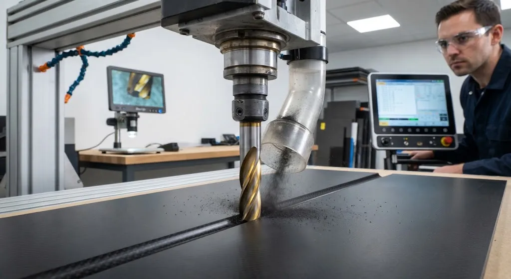
Machining carbon fiber reinforced polymer composites differs fundamentally from metal cutting. CFRP's heterogeneous structure — hard, abrasive carbon fibers embedded in a relatively soft polymer matrix — creates a two-phase cutting environment where tool wear mechanisms, chip formation,
Introduction
Machining carbon fiber reinforced polymer composites differs fundamentally from metal cutting. CFRP's heterogeneous structure — hard, abrasive carbon fibers embedded in a relatively soft polymer matrix — creates a two-phase cutting environment where tool wear mechanisms, chip formation, and surface quality generation follow different rules than conventional machining. Understanding these differences is essential for optimizing tool life, maintaining surface quality, and controlling manufacturing costs in CFRP component production.
Carbide cutting tools dominate CFRP machining due to their hardness, wear resistance, and cost-effectiveness compared to diamond or ceramic alternatives. However, the abrasive nature of carbon fibers causes rapid flank wear and edge rounding that can degrade surface quality within minutes of cutting. This article analyzes the wear mechanisms specific to CFRP machining, evaluates coating technologies that extend tool life, and establishes cutting parameter recommendations for optimal surface finish and productivity.
Wear Mechanisms in CFRP Machining
Tool wear in CFRP machining follows distinct mechanisms compared to metal cutting. The primary wear modes observed in carbide tools include:
- Flank wear: The dominant wear mechanism, caused by rubbing of the tool's flank face against the machined surface. Carbon fibers act as micro-cutters that abrade the tool surface, creating a wear land that grows progressively with cutting distance. Flank wear is the primary determinant of surface quality degradation.
- Crater wear: Occurs on the tool's rake face where chip flow creates friction and heat. In CFRP, crater wear is less severe than in metal cutting because the polymer matrix provides some lubrication, but it contributes to edge weakening and eventual failure.
- Edge rounding: The sharp cutting edge progressively rounds due to abrasive wear, increasing cutting forces and reducing surface quality. Edge rounding is particularly problematic in CFRP because the fibers require sharp edges for clean cutting rather than plowing.
- Delamination-induced damage: When tool wear becomes excessive, cutting forces increase and cause subsurface delamination, fiber pullout, and poor hole quality. This represents a failure mode unique to composite machining.
| Wear Type | Mechanism | Effect on Surface Quality | Critical Threshold | Detection Method |
|---|---|---|---|---|
| Flank wear (VB) | Fiber abrasion against tool flank | Increased roughness, fiber pullout | VB > 0.3 mm (finish), > 0.5 mm (rough) | Optical measurement, surface profilometry |
| Crater wear (KT) | Chip friction on rake face | Edge weakening, chipping | KT > 0.15 mm | Tool maker's microscope |
| Edge rounding | Abrasive wear at cutting edge | Increased forces, fuzzing | Edge radius > 25 μm (finish) | Scanning electron microscopy |
| Chipping | Thermal cycling, fiber impact | Major surface defects | Any visible chip | Visual inspection, tactile |
The abrasive wear rate of carbon fibers on carbide tools is approximately 10-50 times higher than equivalent steel cutting, depending on fiber type, resin system, and cutting parameters. Unidirectional CFRP with high-modulus pitch-based fibers causes the most severe wear, while woven fabrics with standard modulus fibers are more moderate.
Coating Technologies for Extended Tool Life
Tool coatings significantly extend carbide tool life in CFRP machining by providing barrier protection against fiber abrasion and reducing friction at the cutting interface. Several coating technologies are commonly used:
- TiN (Titanium Nitride): The baseline coating for CFRP machining, providing 2-3x tool life improvement over uncoated carbide. TiN's hardness (2,300 HV) resists fiber abrasion, while its golden color便于 wear detection. Cost-effective for medium-volume production.
- TiAlN (Titanium Aluminum Nitride): Offers 3-5x improvement over uncoated carbide with better thermal stability than TiN. The aluminum content forms a protective aluminum oxide layer at cutting temperatures, reducing adhesion and friction. Recommended for high-speed CFRP machining.
- DLC (Diamond-Like Carbon): Provides the best wear resistance for CFRP machining with 5-10x tool life improvement. DLC's extreme hardness (1,000-5,000 HV depending on type) and low friction coefficient (0.1-0.2) minimize fiber abrasion. The high cost ($50-150 per tool) is justified in high-volume production or when surface quality is critical.
- PCD (Polycrystalline Diamond) tips: The ultimate solution for CFRP machining with 20-50x tool life improvement. PCD's diamond hardness (5,000-8,000 HV) provides essentially unlimited wear resistance against carbon fibers. High initial cost ($200-500 per tool) but lowest per-part cost in volume production.
Optimal Cutting Parameters
CFRP machining requires different parameter strategies than metal cutting. The goal is to achieve clean fiber cutting with minimal delamination and acceptable surface finish. Key parameter recommendations include:
- Cutting speed: 150-300 m/min for uncoated carbide, 200-500 m/min for coated tools, 500-2,000 m/min for PCD. Higher speeds generally improve surface finish by reducing fiber pullout, but must be balanced against tool life.
- Feed rate: 0.05-0.15 mm/tooth for milling, 0.05-0.20 mm/rev for drilling. Lower feeds reduce delamination but increase cutting time and heat generation. Optimum feed depends on tool diameter, fiber orientation, and laminate thickness.
- Depth of cut: For milling, 0.5-2.0 mm axial depth and 1-5 mm radial width is typical. Climb milling produces better surface finish than conventional milling due to reduced fiber delamination at the entry point.
- Coolant strategy: Compressed air or minimum quantity lubrication (MQL) is preferred over flood coolant in CFRP machining. Flood coolant can cause thermal shock and delamination in some resin systems, while air blast effectively clears chips and provides some cooling.
Surface Quality Metrics and Acceptance Criteria
CFRP surface quality is characterized by several metrics that correlate with tool condition and cutting parameters:
- Surface roughness (Ra): Typical acceptable range is 0.8-3.2 μm for machined CFRP, depending on application. Structural aerospace parts typically require Ra < 1.6 μm, while non-structural components may accept Ra up to 3.2 μm.
- Fiber pullout length: Should be less than 0.5 mm for structural applications. Excessive pullout indicates dull tools or improper cutting parameters.
- Delamination factor: The ratio of delaminated zone diameter to hole diameter in drilling should be less than 1.5 for aerospace acceptance. Higher values indicate excessive thrust forces from worn tools.
- Color change: Discoloration or browning of the machined surface indicates thermal damage from tool friction. This is unacceptable for cosmetic surfaces and may indicate reduced structural integrity.
Frequently Asked Questions
How often should carbide tools be changed when machining CFRP?
Tool change intervals depend heavily on the specific CFRP material, tool coating, and cutting parameters. For uncoated carbide cutting standard modulus woven CFRP, expect 20-50 meters of cutting length before flank wear reaches 0.3 mm. Coated carbide (TiAlN) extends this to 60-150 meters, while PCD tools can cut 500-2,000 meters before replacement. In practice, monitor surface quality — when roughness exceeds specification or fiber pullout becomes visible, change tools immediately. Establish tool life baselines by running test cuts and measuring wear with a tool maker's microscope at regular intervals.
What is the most common cause of poor surface finish in CFRP machining?
The most common cause is tool wear — specifically flank wear exceeding the critical threshold (VB > 0.3 mm for finish machining). As the flank wear land grows, the tool's effective cutting geometry changes, increasing rubbing and reducing clean fiber cutting. The second most common cause is incorrect cutting parameters: feeds that are too high cause fiber pullout and delamination, while feeds that are too low increase heat generation and matrix melting. Third, improper tool path strategy (conventional milling instead of climb milling, or incorrect drill point geometry) can cause fiber breakout at entry and exit points.
Can standard metal cutting tools be used for CFRP, or are specialized tools required?
Standard uncoated carbide tools can cut CFRP but will wear rapidly — typically 10-50x faster than cutting steel. For one-off prototyping or low-volume production, standard tools are acceptable if surface quality requirements are modest. For production volumes, specialized CFRP tools with appropriate coatings (TiN, TiAlN, or DLC) are strongly recommended. The coating cost ($5-50 per tool) is quickly recovered through extended tool life and consistent surface quality. For high-volume aerospace production, PCD-tipped tools are the standard choice despite their higher initial cost.
Conclusion
Carbide tool wear in CFRP machining is dominated by fiber abrasion mechanisms that differ fundamentally from metal cutting wear. Understanding flank wear progression, edge rounding, and delamination-induced failure modes enables rational tool selection and parameter optimization. Coating technologies — from baseline TiN through high-performance DLC and PCD — provide 2-50x tool life improvements that directly reduce manufacturing costs and improve surface quality consistency.
For manufacturers machining CFRP components, the practical path involves establishing tool life baselines for specific material-coating-parameter combinations, implementing systematic tool wear monitoring, and optimizing cutting parameters for the balance of tool life, surface quality, and productivity. Explore our carbon fiber composite materials, including machining-grade laminates optimized for cutting performance, or contact our engineering team to discuss machining recommendations for your specific CFRP application.
Related Articles
- Bio-Based Carbon Fiber Precursors: Lignin and Polyethylene for Low-Cost Production
- Large-Tow Carbon Fiber Cost Analysis: 48K vs 60K Price-Performance Comparison
- Carbon Fiber-Resin Interface Bonding: Surface Treatment and Coupling Agent Optimization
- Digital Twin for Carbon Fiber Manufacturing: Real-Time Process Monitoring and Defect Prevention
- Thermoplastic Carbon Fiber Welding for Automotive: Ultrasonic and Induction Welding Process Windows
- Large-Tow Carbon Fiber Wet Spinning: Process Optimization for 48K/60K Production Efficiency
Interested in Custom Carbon Fiber Products?
Contact our team for competitive pricing and technical specifications.
Get a QuoteRelated Products

Carbon Fiber Fishing Rod Blank
High-quality carbon fiber fishing rod blank manufactured from multiple grades of Toray carbon fiber cloth. Available in a wide range of lengths, powers, and actions for freshwater and saltwater applications. Suitable for OEM rod building.
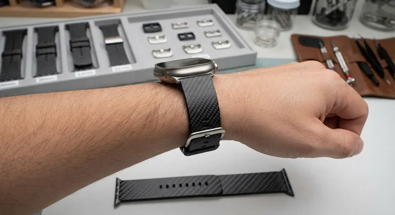
Carbon Fiber Watch Strap — 20mm/22mm Quick-Release
Premium carbon fiber watch strap with quick-release spring bars. Woven from T700 3K twill prepreg with a flexible resin system that conforms to the wrist. Available in 20mm and 22mm lug widths, compatible with Apple Watch, Samsung Galaxy Watch, Garmin, and traditional mechanical watches. Features a stainless steel buckle and carbon fiber keepers. The natural weave pattern makes each strap unique.
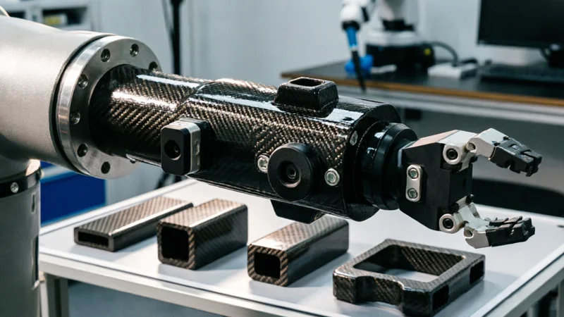
Carbon Fiber Robot End Effector Link — Custom Shape & Sensor Integration
Custom-shaped carbon fiber end effector links for robotic arms. Designed for automation integrators and research labs requiring lightweight, rigid connections between the robot wrist and gripper/tool. Can incorporate sensor mounting bosses, cable routing channels, and quick-change interfaces.

Custom Carbon Fiber Musical Instrument Parts
Carbon fiber components for musical instrument manufacturing offering superior dimensional stability, low weight, and consistent acoustic properties. We produce carbon fiber bows, guitar necks, violin chin rests, drum shells, and wind instrument bodies. Carbon fiber instruments are immune to humidity changes and temperature fluctuations that affect wooden instruments.

Custom Carbon Fiber Medical Device Components
Medical-grade carbon fiber components manufactured for imaging equipment, surgical instruments, and patient support systems. Carbon fiber's radiolucency (X-ray transparency) and high strength-to-weight ratio make it ideal for CT scanner beds, wheelchair frames, surgical robot arms, and MRI-compatible accessories. Biocompatible resin systems available.