
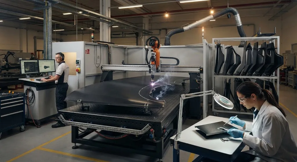
Laser processing of CFRP has moved from laboratory curiosity to production trimming because it offers what mechanical routers cannot: non-contact cutting with no tool wear, high traverse speeds, and the ability to follow complex digital toolpaths without fixturing changes. Aerospace, au
Introduction
Laser processing of CFRP has moved from laboratory curiosity to production trimming because it offers what mechanical routers cannot: non-contact cutting with no tool wear, high traverse speeds, and the ability to follow complex digital toolpaths without fixturing changes. Aerospace, automotive, and marine workshops use lasers to trim cured panels, cut uncured prepreg stacks, drill fastener holes, and scribe laminates before separation. The technology is attractive precisely where conventional machining struggles — thin skins, closed geometries, and cutting programs that change frequently.
The obstacle is the heat-affected zone (HAZ). Carbon fiber conducts heat along the filaments far better than the surrounding epoxy matrix conducts across the thickness, and epoxy begins to decompose around 400 °C. A laser beam that cuts the fibers quickly also heats the resin, and if that heat is not removed fast enough, the matrix burns back from the cut edge, leaving charred, weak, and electrically leaky edges. Every practical laser process for CFRP is therefore an exercise in heat management: deliver enough energy to vaporize the fibers, yet remove the residual heat before the matrix decomposes.
Why CFRP Resists Conventional Laser Cutting
The difficulty comes from the mismatch between fiber and matrix properties. Carbon fibers are refractory: they do not sublime until roughly 3,600 °C. The surrounding epoxy, by contrast, is thermally fragile and starts to lose mechanical integrity well below 400 °C. A beam powerful enough to cut the fibers will inevitably flood the matrix at the cut edge with conducted heat, because the fiber acts as a heat pipe that spreads thermal energy into the laminate.
The failure mechanism is characteristic. The resin in a zone around the kerf pyrolyzes, releasing volatiles and leaving a porous char; the char delaminates from the neighboring intact laminate; and the exposed fiber ends protrude, fray, or wick moisture. The HAZ width in poorly optimized processes ranges from hundreds of micrometers to several millimeters, which is unacceptable for load-bearing edges that must mate with bonded or bolted joints. HAZ and cut speed trade against each other: a shorter, higher-energy interaction cuts faster than a gentle one, but it also deposits its energy before the matrix can shed the heat.
Laser Sources and Their Cutting Characteristics
The choice of laser source determines the achievable HAZ more than any other variable. Four families are commercially relevant for CFRP, and the table below summarizes their typical performance on 1-3 mm laminates:
| Laser Source | Wavelength | Pulse Mode | Typical HAZ | Relative System Cost |
|---|---|---|---|---|
| CO2 laser | 10.6 µm | CW or pulsed | 1,000-3,000 µm | Low |
| Fiber laser | 1.06-1.07 µm | CW or pulsed | 300-800 µm | Low to medium |
| Nanosecond pulsed | 0.355-1.06 µm | Pulsed | 100-300 µm | Medium |
| Ultrashort pulse (ps/fs) | 0.343-1.06 µm | Pulsed | 5-30 µm | High |
The physical reason for the spread is absorption. CO2 radiation at 10.6 µm is absorbed strongly by the organic resin but reflected by the carbon fibers, so the beam burns the matrix and relies on conducted heat to break the fibers — a recipe for a wide HAZ. Laser sources at 1 µm couple better into the fibers because carbon absorbs that wavelength more efficiently. Nanosecond pulses limit the thermal diffusion depth to tens of micrometers per pulse. Picosecond and femtosecond pulses remove material by multiphoton ablation before heat diffuses out of the focal volume, giving nearly char-free edges at the price of lower average power and higher capital cost.
Controlling the Heat-Affected Zone
Practical HAZ control uses five levers that process engineers combine according to the part geometry. High scan speed is the first: moving the beam fast concentrates energy in a small interaction zone and shortens the time available for conduction. The second is a multi-pass strategy, in which several shallow passes remove the laminate layer by layer instead of one deep, thermalizing cut; the passes are cheap in time but dramatically reduce char depth. The third is water-jet-assisted cutting, in which a thin, high-pressure water jet guides the beam and simultaneously quenches the cut flanks. The fourth is beam shaping — ring-shaped or twin-focus beams that vaporize the fiber core while confining thermal load to a narrow zone. The fifth is an inert gas assist that sweeps away molten debris and hot plasma, preventing oxidation and re-deposition on the edge.
For production trimming, the combination that appears most often in modern cells is a pulsed fiber laser with a fast galvo scanner, a multi-pass toolpath, and nitrogen assist gas. This combination keeps the HAZ below roughly 100 µm on 2-3 mm panels while sustaining cutting speeds of 2-6 m/min, depending on thickness and ply orientation. The residual HAZ still requires verification by cross-section microscopy on first articles, because ply stacking changes local thermal behavior more than suppliers expect.
Kerf Quality and Typical Defects
Edge defects in laser-processed CFRP are consistent and diagnosable. The most destructive for structural parts are listed below:
- Charring and resin recession: The matrix burns back from the cut line, leaving a dark, porous zone with degraded shear strength. Caused by excessive heat input or insufficient assist gas.
- Exit delamination: The laminate splits apart at the beam exit side when pyrolysis pressure and thermal expansion overcome the local interlaminar strength. Worse on thick panels and with single deep passes.
- Fiber protrusion and fraying: Unsupported fiber ends extend beyond the cut edge after the resin recedes. They attract moisture, fray in handling, and complicate bonded joints.
- Kerf taper: The cut width differs between beam entry and exit because the beam diverges and the HAZ grows with depth. Taper of 0.1-0.5 mm per side is typical and must be budgeted in the toolpath.
Acceptance criteria for aerospace and automotive edge trim usually set a maximum char width and a maximum protruding fiber length, verified on cross-section micrographs. The cost of rework is high, so first-article inspection of the HAZ is a fixed step in any laser qualification program.
Throughput and Cost Trade-Offs
Throughput is where laser processing shines and where it pays a tax. A 2-4 kW fiber laser trims 2 mm CFRP at 4-8 m/min with a HAZ of 300-800 µm; a nanosecond pulsed system drops to 1-3 m/min but halves the HAZ; an ultrashort-pulse system delivers the smallest HAZ yet, but average power limits it to below 1 m/min on thick sections. In practice, the throughput decision is an edge-quality decision: parts that are bonded or cosmetically visible justify the slower process, while sacrificial trim lines and non-visible edges tolerate a wider HAZ.
Cost structure follows capital rather than consumables. Laser cells have no cutting tool inventory, no dulling, and no coolant disposal, but the source, scanning optics, and fume extraction represent a substantial upfront investment. Nanosecond and fiber systems amortize well at production volumes above a few thousand parts per year; ultrashort-pulse systems are economical primarily for high-value aerospace parts where edge quality gates the entire assembly. The table below compares the most common CFRP trimming routes:
| Criterion | Fiber Laser Cutting | CNC Routing | Abrasive Waterjet |
|---|---|---|---|
| Edge quality (HAZ or damage) | Good to excellent | Excellent | Excellent |
| Tool wear | None | High | Nozzle wear only |
| Cutting speed (2 mm panel) | 2-8 m/min | 0.5-2 m/min | 0.3-1 m/min |
| Secondary operations | HAZ inspection | Deburring | Drying, edge sealing |
| Capital cost | Medium to high | Low | Medium |
| Best fit | High-volume contours, thin skins | Thick structures, holes, 3D edges | Thick stacks, insensitive materials |
For a typical aerospace program, the practical split is: waterjet for thick, complex stacks; routing for 3D and thick-section trimming; laser for thin skins, scribing, and high-volume 2D contours. The routes are complementary, and modern workshops run all three rather than forcing a single technology.
Frequently Asked Questions
Is laser cutting of CFRP safe in a production environment?
Yes, when the cell is engineered correctly. Cutting CFRP releases pyrolysis gases and fine carbon dust, so the workstation must include enclosed optics, local exhaust ventilation, and particulate filtration sized for the expected fume load. The beam path itself is contained within the cell enclosure with interlocked doors. Operators follow the same laser-safety class requirements as any industrial laser installation: enclosure interlocks, designated beam plane, and eye protection for open-beam servicing.
Can lasers drill through-thickness holes in CFRP without delamination?
Drilling is more demanding than through-cutting because the hole wall has no free edge to vent pyrolysis pressure. With a trepanning strategy — cutting the hole contour with a small beam instead of boring a blind hole — and multi-pass parameters, producers routinely achieve hole quality comparable to mechanical drilling at 2-6 mm thickness. Ultrashort-pulse lasers give the cleanest hole walls, but for production rates nanosecond trepanning with inert assist gas is the pragmatic choice. Entry and exit delamination must still be inspected on first articles.
What thickness of CFRP can a laser cut economically?
In practice, laser cutting is economical and reliable up to roughly 5-6 mm. Thin skins in the 1-3 mm range cut fastest with the best HAZ control. Above 10 mm, the HAZ grows, taper becomes severe, and throughput collapses because the beam must make many passes; abrasive waterjet or CNC routing take over for thick sections. Hybrid approaches exist for moderate thickness, but most shops draw the line at about 6 mm for production laser trimming.
Conclusion
Laser processing of CFRP is a mature production tool when the heat-affected zone is understood and controlled. The source choice sets the achievable HAZ, the scan and assist-gas strategy holds it in production, and the throughput target decides where laser trimming fits alongside waterjet and routing. Buyers specifying laser-trimmed carbon fiber parts should request HAZ verification data, edge acceptance criteria, and demonstrated cutting speed — not just a clean-looking sample. For manufacturers evaluating the route, the decisive question is whether the part geometry and volume justify the capital, because the technology rewards programs that use it continuously.
YongXian supplies carbon fiber fabrics, unidirectional prepreg, and reinforcement materials used in laser-cut and mechanically trimmed components across aerospace, automotive, and marine programs. Explore our carbon fiber product range or contact our engineering team to discuss material systems and edge-finishing support for your application.
Part of topic
Related Articles
- Bio-Based Carbon Fiber Precursors: Lignin and Polyethylene for Low-Cost Production
- Large-Tow Carbon Fiber Cost Analysis: 48K vs 60K Price-Performance Comparison
- Carbon Fiber-Resin Interface Bonding: Surface Treatment and Coupling Agent Optimization
- Digital Twin for Carbon Fiber Manufacturing: Real-Time Process Monitoring and Defect Prevention
- Thermoplastic Carbon Fiber Welding for Automotive: Ultrasonic and Induction Welding Process Windows
- Large-Tow Carbon Fiber Wet Spinning: Process Optimization for 48K/60K Production Efficiency
Interested in Custom Carbon Fiber Products?
Contact our team for competitive pricing and technical specifications.
Get a QuoteRelated Products

Carbon Fiber Fishing Rod Blank
High-quality carbon fiber fishing rod blank manufactured from multiple grades of Toray carbon fiber cloth. Available in a wide range of lengths, powers, and actions for freshwater and saltwater applications. Suitable for OEM rod building.
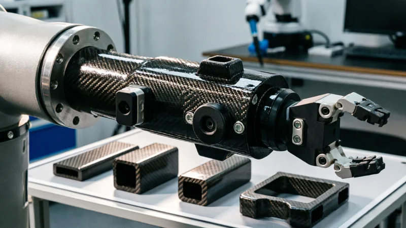
Carbon Fiber Robot End Effector Link — Custom Shape & Sensor Integration
Custom-shaped carbon fiber end effector links for robotic arms. Designed for automation integrators and research labs requiring lightweight, rigid connections between the robot wrist and gripper/tool. Can incorporate sensor mounting bosses, cable routing channels, and quick-change interfaces.

Custom Carbon Fiber Medical Device Components
Medical-grade carbon fiber components manufactured for imaging equipment, surgical instruments, and patient support systems. Carbon fiber's radiolucency (X-ray transparency) and high strength-to-weight ratio make it ideal for CT scanner beds, wheelchair frames, surgical robot arms, and MRI-compatible accessories. Biocompatible resin systems available.

Custom Carbon Fiber Musical Instrument Parts
Carbon fiber components for musical instrument manufacturing offering superior dimensional stability, low weight, and consistent acoustic properties. We produce carbon fiber bows, guitar necks, violin chin rests, drum shells, and wind instrument bodies. Carbon fiber instruments are immune to humidity changes and temperature fluctuations that affect wooden instruments.
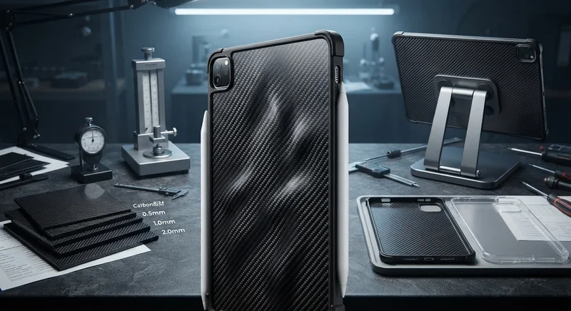
Carbon Fiber Tablet Case — Ultra-Light Protective Shell
Lightweight carbon fiber protective case for tablets and iPads. Molded from T700 3K prepreg with reinforced corner protection. Adds minimal weight while providing superior rigidity and drop protection compared to polycarbonate or silicone cases. Ideal for field workers, enterprise deployments, and professionals requiring durable tablet protection.