
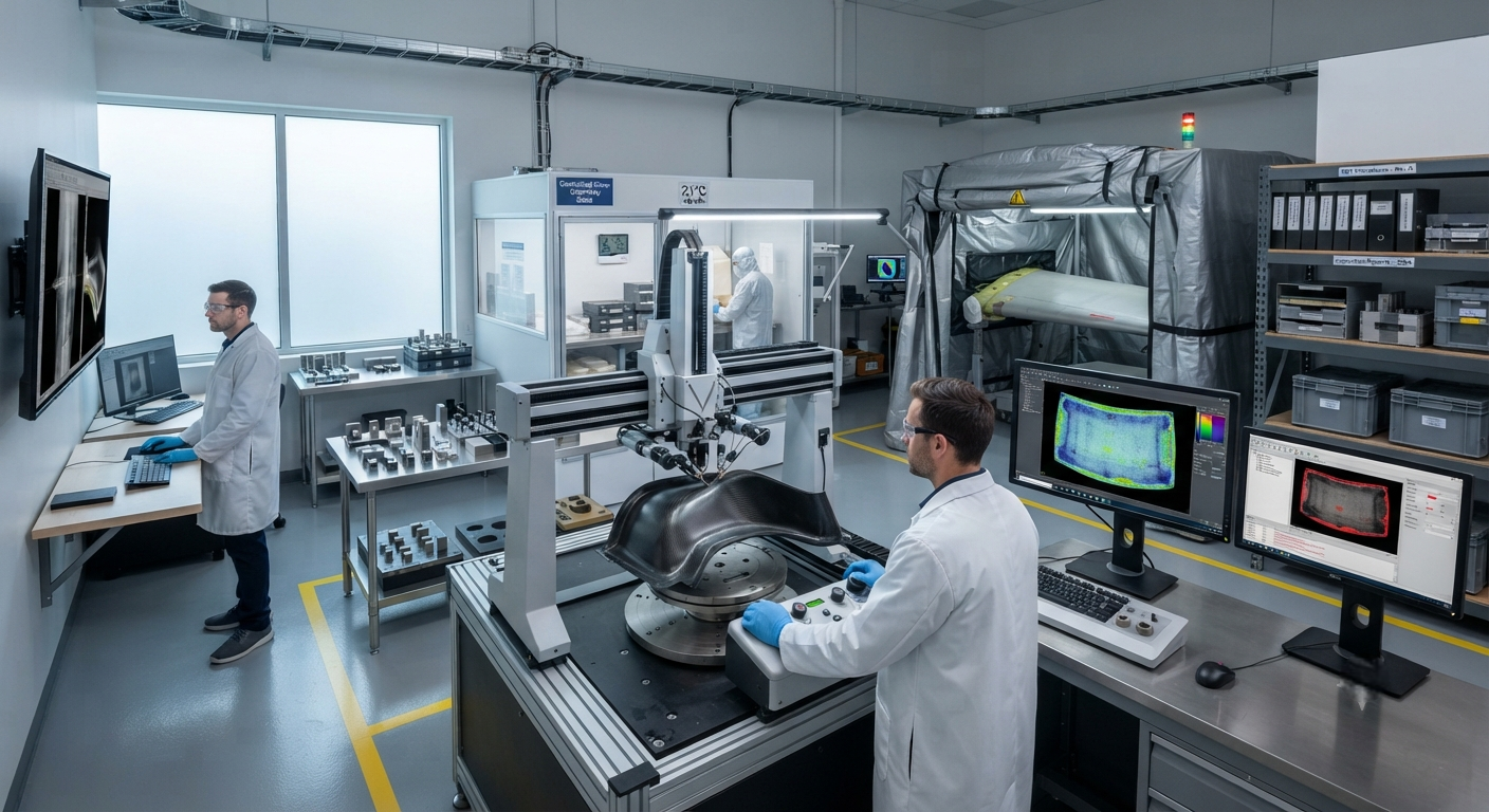
Comprehensive B2B guide to selecting a qualified NDT testing laboratory for carbon fiber composite components. Covers the six critical defect types in CFRP (delamination, porosity, disbond, fiber waviness, BVID, FOD) with primary detection methods, NDT technique selection criteria (UT, CT, thermography, shearography, tap testing), accreditation requirements (ISO/IEC 17025, NAS 410/EN 4179, NADCAP AC7114) with a real-data comparison table of six accreditation frameworks, structured qualification audit checklist for B2B buyers, and industry-specific NDT requirements for aerospace, automotive, wind energy, marine, and industrial sectors. Includes sector rejection rate data, cost analysis ($150K-$500K annual NDT cost for mid-volume manufacturers), and AI/ML impact assessment.
Introduction to NDT for Carbon Fiber Components in B2B Manufacturing
Non-Destructive Testing (NDT) is a critical quality assurance process in the carbon fiber composites industry. Unlike metallic components, where defects such as cracks, porosity, or inclusions can often be detected through visual inspection or simple dimensional gauging, carbon fiber reinforced polymer (CFRP) components require specialised inspection techniques due to their anisotropic material properties, layered construction, and the hidden nature of critical defects such as delamination, disbond, and ply waviness. For B2B buyers procuring carbon fiber parts—whether for aerospace, automotive, wind energy, or industrial applications—selecting a qualified NDT testing laboratory is as important as selecting the right material system and manufacturing process.
The global carbon fiber NDT services market was valued at approximately $680 million in 2025 and is projected to reach $1.15 billion by 2030, growing at a CAGR of 11.2%. This growth is driven by increasing quality requirements in aerospace (FAA Part 21, EASA Part 21G), expanding use of carbon fiber in safety-critical automotive structures (ISO 26262 ASIL D), and the rapid scaling of wind turbine blade manufacturing requiring 100% ultrasonic inspection of spar caps and shear webs. For procurement professionals, understanding NDT laboratory accreditation standards, technique selection criteria, and qualification requirements is essential for ensuring component quality and supply chain compliance.
Key Defect Types in Carbon Fiber Composites and Their Detection
Understanding the defect landscape is the first step in selecting appropriate NDT methods. Carbon fiber composite defects fall into several categories, each with specific detection requirements:
- Delamination: Separation between adjacent plies of the laminate, typically caused by impact damage, manufacturing process deviations (insufficient consolidation pressure, resin starvation), or thermal cycling stresses. Delaminations are the most critical defect type in CFRP because they significantly reduce compressive strength and can propagate under cyclic loading. Detection typically requires ultrasonic testing (UT) or laser shearography. Minimum detectable delamination size for critical aerospace components is typically 6 mm (0.25 in) diameter per ASTM E2580.
- Porosity and voids: Entrapped air or volatiles within the laminate or at ply interfaces, resulting from inadequate debulking during layup, insufficient vacuum during cure, or expired prepreg materials. Porosity is expressed as a percentage of cross-sectional area. Aerospace-grade components typically require porosity below 1% by volume, while industrial-grade components may accept up to 3–5%. Ultrasonic attenuation measurement and X-ray computed tomography (CT) are the primary detection methods.
- Disbond: Separation at adhesive-bonded joints or at the interface between the composite laminate and a bonded core (honeycomb or foam). Disbonds are critical in sandwich panel constructions for aerospace and marine applications. Detection methods include ultrasonic testing, tap testing (coin-tap method per ASTM D6415), and thermography for large-area screening.
- Fibre waviness (wrinkling): Deviation of fibres from their intended orientation, often occurring during complex-geometry layup (e.g., radius fill areas, Joggles) or during consolidation of thick laminates. Fibre waviness reduces compressive strength by 15–40% depending on severity. Detection requires ultrasonic C-scan imaging or CT scanning.
- Impact damage (barely visible impact damage — BVID): Low-velocity impact events that may leave little or no visible surface mark but cause significant internal delamination and matrix cracking. BVID is a primary concern for carbon fiber aircraft structures per FAA AC 20-107B. Detection requires ultrasonic inspection or thermography.
- Inclusions and foreign object debris (FOD): Contaminants embedded in the laminate, such as release film fragments, tool debris, or foreign fibres. Detection depends on inclusion size and material contrast with carbon fiber. Large inclusions (≥2 mm) are detectable by UT or X-ray; smaller inclusions may require CT scanning at high resolution (≤50 µm voxel size).
| Defect Type | Criticality (1–5) | Primary Detection Method | Secondary Method | Typical Acceptance Limit | Industry Standard |
|---|---|---|---|---|---|
| Delamination | 5 | Ultrasonic C-scan (10–15 MHz) | Shearography, CT | None ≥ 6 mm dia. (aero) | ASTM E2580, EN 1330-4 |
| Porosity (>1%) | 4 | UT attenuation (backwall echo) | CT, acid digestion | <1% by vol. (aero); <3% (industrial) | ASTM D2734, EN 2564 |
| Disbond | 5 | Ultrasonic (pulse-echo) | Tap test, thermography | None ≥ 12 mm (aero) | ASTM D6415, EN 12680-3 |
| Fibre waviness | 3 | Ultrasonic C-scan | CT, micrographic cross-section | Waviness ratio < 1:15 | ASTM E2580, EN 2561 |
| BVID impact | 5 | Ultrasonic (through-transmission) | Thermography, laser shearography | No growth after 2× service life fatigue | FAA AC 20-107B, ASTM D7136 |
| Inclusions/FOD | 3 | X-ray CT (≤50 µm voxel) | Ultrasonic | None ≥ 2 mm (aero) | ASTM E2662, EN 2557 |
NDT Technique Selection Based on Material and Geometry
The selection of appropriate NDT techniques depends on several interdependent factors. A qualified laboratory should demonstrate competence across multiple techniques and provide clear rationale for technique selection based on the specific component being inspected:
- Ultrasonic Testing (UT): The most widely used NDT method for carbon fiber composites. Pulse-echo UT uses a single transducer to send and receive sound waves; through-transmission UT uses separate transmitter and receiver transducers. Phased-array ultrasonic testing (PAUT) is increasingly preferred for complex geometries, providing electronic beam steering and focusing without moving the probe. Frequency selection is critical: 5 MHz provides penetration up to 100 mm in CFRP but detects defects ≥ 1.5 mm; 10–15 MHz offers resolution down to 0.5 mm but limited penetration (≤40 mm). Laboratories undertaking aerospace work must demonstrate UT capability per NAS 410/EN 4179 certification.
- X-ray Computed Tomography (CT): The gold standard for complex-geometry CFRP components where internal defect characterisation is required. CT provides volumetric data enabling measurement of defect position, size, and morphology in three dimensions. State-of-the-art laboratory CT systems for carbon fiber inspection achieve voxel resolutions of 5–50 µm with 225–450 kV microfocus X-ray sources. CT is essential for inspection of bond lines in complex co-cured structures, porosity distribution analysis in thick laminates, and dimensional verification of internal features.
- Thermography: Active thermography — using flash lamps (pulsed thermography) or ultrasonic excitation (sonic thermography) — provides rapid (seconds per area) inspection of large surface areas. Best suited for near-surface defect detection (≤3 mm depth for pulsed thermography; ≤8 mm for sonic thermography). Primary applications include production-line screening of sandwich panels for disbonds, impact damage detection in wind turbine blades, and in-service inspection of aircraft composite control surfaces.
- Laser Shearography: An optical NDT method that measures surface strain gradients under controlled thermal or vacuum loading. Extremely sensitive to near-surface disbonds and delaminations in thin-skinned sandwich structures (skin thickness ≤3 mm). Widely used in aerospace for inspection of honeycomb panels and in wind energy for blade root and adhesive bond line inspection. Shearography is the preferred method for in-field composite repair verification per Boeing D6-82347 and Airbus AITM 6-0030.
- Tap Testing (Acoustic Resonance): The simplest and most portable NDT method. A lightweight instrumented hammer or automated tapping device measures the acoustic response of the component. Disbonds and delaminations produce a characteristic dull sound with reduced resonant frequency. Modern instrumented tap testers (e.g., Woodpecker, MIA) provide quantitative frequency and amplitude data. Acceptable as a screening method for non-critical components per ASTM D6415, but insufficient sensitivity for aerospace primary structures.
Accreditation and Certification Requirements for NDT Laboratories
The credibility of an NDT testing laboratory for carbon fiber components is established through third-party accreditation to internationally recognised standards. B2B buyers should verify the following accreditations when qualifying a laboratory:
ISO/IEC 17025 — General Competence of Testing Laboratories
ISO/IEC 17025 is the foundational international standard for laboratory competence. Laboratories accredited to ISO/IEC 17025 by a recognised accreditation body (e.g., ANAB, UKAS, DAkkS, CNAS, COFRAC) have demonstrated proficiency in: (a) establishing and maintaining a quality management system for test operations; (b) ensuring personnel competence through documented training, qualification, and recertification programs; (c) using validated or standardised test methods with demonstrated measurement uncertainty; (d) participating in inter-laboratory proficiency testing programmes; (e) maintaining calibration traceability for all measurement equipment to national or international standards. As of 2026, there are approximately 1,850 ISO/IEC 17025-accredited testing laboratories worldwide with composite materials testing in their scope, with the highest concentrations in the United States (420), Germany (310), China (280), Japan (120), and France (95).
NAS 410 / EN 4179 — NDT Personnel Qualification
NDT personnel performing inspection of aerospace carbon fiber components must be certified to NAS 410 (USA) or EN 4179 (Europe), which establish three qualification levels: Level I (trainee, operates under supervision), Level II (independently performs and interprets NDT), and Level III (develops procedures, approves techniques, trains and certifies Level I/II personnel). Laboratories serving aerospace customers must employ NDT personnel with current certifications in the specific NDT method(s) being deployed, with documented recertification at intervals not exceeding five years. B2B buyers should request copies of Level III certifications and the laboratory's written practice document that defines certification scope for each method.
A2LA / PRI / NADCAP — Composites NDT-Specific Accreditations
For aerospace-grade carbon fiber component testing, NADCAP accreditation (National Aerospace and Defence Contractors Accreditation Program) is increasingly mandatory. NADCAP audit checklists for NDT (AC7114 series) cover additional requirements beyond ISO/IEC 17025, including: (a) specific technique parameters for composite NDT methods; (b) demonstrated Probability of Detection (POD) for targeted defect types per MIL-HDBK-1823A; (c) documented Procedure for NDT of composite materials (Nadcap NDT Checklist for Composites); (d) Annual audit cycle with on-site assessment by qualified NADCAP aerospace auditors. Laboratories without NADCAP accreditation may be limited to non-aerospace industrial applications or require additional customer-specific qualification audits.
| Accreditation / Standard | Scope | Industry Mandate | Audit Frequency | Typical Cost (Annual) | Geographic Recognition |
|---|---|---|---|---|---|
| ISO/IEC 17025 | General lab competence | All industries (foundational) | 18 months | $8,000–$15,000 | Global (ILAC mutual recognition) |
| NAS 410 / EN 4179 | NDT personnel qualification | Aerospace (mandatory) | 5 years (recertification) | $2,000–$5,000 per person | US / Europe respectively |
| NADCAP (AC7114) | Aerospace composites NDT | Aerospace (prime contractors) | 12 months | $12,000–$25,000 | Global (PRI managed) |
| CNAS (China) | Lab competence (ISO 17025 equivalent) | China domestic aerospace / auto | 18 months | ¥60,000–¥120,000 | China (APAC mutual recognition) |
| A2LA (USA) | Composites testing scope | US defence / automotive | 24 months | $6,000–$10,000 | US / ILAC MRA |
| JIS Q 17025 (Japan) | Lab competence (ISO 17025 equivalent) | Japan aerospace / automotive | 24 months | ¥400,000–¥800,000 | Japan / APAC MRA |
Qualification Audits: What B2B Buyers Should Verify
Before engaging an NDT laboratory for carbon fiber component testing, B2B buyers should conduct a structured qualification audit covering the following areas:
- Personnel qualifications: Verify that all NDT technicians have current Level II or Level III certifications in the NDT methods to be deployed. Request the laboratory's NDT personnel roster with certification numbers, method scope, and expiry dates. Verify that Level III personnel hold current certification from an accredited certifying body (e.g., ASNT, BINDT, DGZfP, COFREND). For aerospace work, confirm NAS 410/EN 4179 compliance.
- Equipment calibration and capability: Review calibration certificates for all NDT equipment (UT flaw detectors, phased-array instruments, CT scanners, thermography cameras) with traceability to national standards (NIST, PTB, NMIJ). Verify that equipment specifications are adequate for the intended inspection: UT systems should demonstrate signal-to-noise ratio ≥ 6:1 per ASTM E317; CT systems should provide spatial resolution adequate to detect the required minimum defect size.
- Probability of Detection (POD) studies: For safety-critical applications, the laboratory should provide POD data for each NDT method and component type. MIL-HDBK-1823A provides the statistical framework for POD demonstration, requiring ≥ 60 data points per method/component combination. A POD of 90/95 (90% detection probability with 95% confidence) is the typical acceptance threshold for aerospace composite inspection.
- Procedure qualification: The laboratory should have written NDT procedures (techniques) for each method and component type, including: scan plan, calibration standards and frequency, scanning parameters (gain, time-corrected gain, gate settings for UT; kV, mA, filter for CT; heat pulse duration for thermography), acceptance criteria, and documentation requirements. Procedures should reference applicable industry standards.
- Reference standards: The laboratory should maintain representative reference standards (calibration blocks) with known defects — including flat-bottom holes, side-drilled holes, simulated delaminations (PTFE insert films), and porosity reference specimens — traceable to national standards. These are essential for technique set-up and sensitivity verification.
- Data management and traceability: Each inspected component must be uniquely identified with traceability to: (a) inspection data files (C-scan images, CT volume data, thermography sequences); (b) inspector identification; (c) date of inspection; (d) technique/calibration used; (e) acceptance/rejection decision with documented justification. Digital data retention policies should meet customer requirements (typically minimum 10 years for aerospace components).
Industry-Specific Requirements by Sector
Different end-use sectors impose distinct NDT requirements for carbon fiber components. The following table summarises the key NDT specifications by industry:
| Sector | Primary NDT Method | Key Standards | Typical Rejection Rate | Sampling Requirement | Additional Requirements |
|---|---|---|---|---|---|
| Aerospace (primary structures) | PAUT (phased array) + CT | FAA AC 20-107B, ASTM E2580, EN 4179 | 3–8% | 100% | POD 90/95; NADCAP; digital data archive 10+ years |
| Automotive (structural) | UT + thermography | ISO 26262, VDA 675260, ASTM D7136 | 2–5% | 100% safety-critical; batch sampling for non-critical | Production-rate capable (30–120 s per part) |
| Wind energy (blades) | UT through-transmission + shearography | DNV-ST-0376, IEC 61400-23, GL 2012 | 5–12% | 100% spar cap + shear web; bond line sampling | In-field capability; blade lengths 40–115+ m |
| Marine (structural) | UT pulse-echo + tap test | Lloyd's Register, DNV-CG-0288, ISO 12215 | 4–10% | 100% primary bonds; sampling for secondary structures | Moisture-resistant UT couplant; field-portable equipment |
| Industrial / sporting goods | Tap test + visual inspection | Customer-specific or general ASTM standards | 1–5% | Sampling per AQL (ANSI/ASQ Z1.4) | Cost-driven; rapid inspection cycles |
Frequently Asked Questions
What is the minimum acceptable ultrasonic testing frequency for carbon fiber aerospace components?
For aerospace-grade carbon fiber components, the minimum UT frequency is typically 5 MHz for general inspection of laminate structures up to 40 mm thickness. For thin laminates (≤ 8 mm) where fine defect resolution is required, 10–15 MHz transducers are recommended, providing sensitivity to delaminations as small as 0.5 mm diameter. For thick laminates (> 40 mm), 2.25–5 MHz is preferred for adequate penetration. The specific frequency selection must be documented in the NDT procedure and demonstrated through sensitivity verification on a reference standard with known defect sizes. Per NAS 410/EN 4179, the laboratory's Level III must approve the technique specification including frequency selection.
How does the NDT approach differ between virgin (new) carbon fiber parts and in-service inspection?
Virgin part NDT is performed in a controlled laboratory environment with full access to the component and established reference standards. The focus is on detecting manufacturing defects (porosity, delamination, disbond, fiber waviness) against defined acceptance criteria. In-service inspection, by contrast, is often performed in the field (aircraft hangar, wind farm, vessel at dock) with limited access, ambient conditions that may affect couplant performance or thermal imaging quality, and the additional challenge of detecting service-induced damage (impact, fatigue cracks, moisture ingress, lightning strike damage for wind turbine blades). Field NDT may use simplified techniques with reduced sensitivity but broader area coverage. The threshold for defect detection in service is typically larger (12 mm versus 6 mm) because the objective is to detect damage that could compromise continued safe operation rather than manufacturing quality control.
What is the typical cost range for NDT inspection of carbon fiber components?
NDT inspection costs for carbon fiber components vary significantly by method, component size, complexity, and production volume. Typical costs as of 2026: Manual UT inspection: $50–$150 per hour per technician (laboratory) to $200–$400 per hour (field service including travel). Automated UT C-scan: $500–$2,000 per square metre of inspected area, with minimum charges of $800–$1,500 per setup. X-ray CT scanning: $200–$800 per scan for small components (< 100 mm envelope) suitable for industrial CT systems; $2,000–$15,000 per scan for large components (600 mm+ envelope) requiring high-energy linear accelerator CT systems. Thermography: $100–$400 per square metre for large-area production screening. Shearography: $300–$800 per square metre for aerospace sandwich panels. Annual NDT cost for a typical mid-volume carbon fiber parts manufacturer (10,000–20,000 parts per year) ranges from $150,000 to $500,000 depending on sector-specific requirements and defect acceptance criteria.
Can the same NDT laboratory certify carbon fiber components for multiple industries (aerospace, automotive, wind)?
Yes, a single laboratory can serve multiple industries provided they maintain the appropriate accreditations for each sector. However, practical limitations exist: (a) Aerospace NDT requires NADCAP accreditation and NAS 410/EN 4179-certified personnel, which adds significant cost and procedural overhead that may not be justified for non-aerospace work; (b) Wind energy blade inspection requires the laboratory to operate at blade manufacturing facilities or wind farm sites, with mobile NDT equipment and personnel capable of working at height — a different operational model from a fixed aerospace laboratory; (c) Automotive high-volume production requires NDT cycle times of 30–120 seconds per part, often using automated inline inspection systems, which is a different operational paradigm from aerospace-style batch inspection. Laboratories typically specialise in one or two adjacent sectors. A combined aerospace/defence laboratory serving both sectors is common; adding wind energy blade inspection requires separate investment in mobile shearography and UT systems plus field-service personnel training.
What are the requirements for NDT procedure qualification for a new carbon fiber component design?
When a new carbon fiber component is introduced, the NDT procedure must be qualified through the following steps: (1) Defect criticality assessment — determine which defect types are most critical for the component's structural function, typically through failure modes and effects analysis (FMEA) per SAE ARP5580; (2) Reference standard fabrication — manufacture representative calibration blocks containing known defects (flat-bottom holes, simulated delaminations via PTFE inserts) at the sizes and locations corresponding to critical defect types; (3) Technique development — establish scanning parameters (probe frequency, focal law for PAUT, voltage/filter for CT) using the reference standards; (4) Sensitivity demonstration — verify that the technique can detect the minimum critical defect size with POD ≥ 90/95 per MIL-HDBK-1823A; (5) Procedure documentation — write a detailed NDT procedure including scan plan, calibration, acceptance criteria, and data recording requirements; (6) Customer approval — submit the qualified procedure to the customer or prime contractor for acceptance and addition to the approved technique list. This process typically takes 4–12 weeks depending on component complexity and prior experience with similar geometries.
How do artificial intelligence and machine learning impact NDT for carbon fiber composites?
AI/ML applications in composite NDT are advancing rapidly as of 2026. Key developments include: (a) Automated defect recognition (ADR) for ultrasonic C-scan data — deep learning models (primarily convolutional neural networks) trained on labelled C-scan data can classify defects with reported accuracy of 92–97% for delamination, porosity, and disbond detection, reducing inspection labor by 40–60% in production environments; (b) CT image reconstruction acceleration — generative AI models reduce CT scan time by 50–70% by reconstructing high-quality images from undersampled projection data using compressed sensing and neural network-based denoising; (c) Defect segmentation and measurement — AI-based segmentation tools provide automated measurement of defect dimensions (area, perimeter, aspect ratio) within 0.1 mm accuracy, eliminating operator-to-operator measurement variability; (d) Predictive maintenance analytics — ML models trained on in-service inspection data predict delamination growth rates and remaining useful life of composite components, enabling condition-based maintenance. B2B buyers evaluating NDT laboratories with AI capabilities should verify that the AI models have been validated on relevant composite material systems and defect types, and that the laboratory maintains human-in-the-loop verification for all AI-generated inspection decisions.
Part of topic
Related Articles
- Recycled Carbon Fiber Market Forecast 2030: Technology Maturity and Commercialization Path
- South Korea Carbon Fiber Market 2026: Hydrogen Economy and Shipbuilding Innovation
- Wind Turbine Blade Leading Edge Protection 2026: Polyurethane, Tape, and Metallic Shield Solutions
- China Carbon Fiber Overcapacity 2026: Price War Impact and Industry Consolidation
- India Carbon Fiber Market 2026: Wind Energy, Aerospace, and Defense Expansion
- PAN Precursor Market 2026: Acrylonitrile Supply and Carbon Fiber Cost Structure
Interested in Our Products?
Contact our team for competitive pricing and technical specifications.
Get a QuoteRelated Products

Custom Carbon Fiber Medical Device Components
Medical-grade carbon fiber components manufactured for imaging equipment, surgical instruments, and patient support systems. Carbon fiber's radiolucency (X-ray transparency) and high strength-to-weight ratio make it ideal for CT scanner beds, wheelchair frames, surgical robot arms, and MRI-compatible accessories. Biocompatible resin systems available.

Carbon fiber standard plate-3k stripe
Lightweight, ultra-rigid standard sheets for drone fuselages, robot housings, facades and structural applications.

Square Carbon Fiber Tube — 3K Twill T700
Square cross-section carbon fiber tube manufactured with 3K twill weave for torsional strength. Preferred for structural frames, trusses, and support columns where rectangular geometry offers design flexibility.

Carbon Fiber Plate — 3K Twill T700 3.0mm
Medium-thickness 3.0mm carbon fiber plate offering significantly higher load capacity while maintaining attractive 3K twill finish. Suitable for structural brackets, reinforcement plates, and load-bearing panels.

Carbon Fiber Plate — 3K Twill T700 1.5mm
Thin 1.5mm carbon fiber plate with 3K twill weave surface. Lightweight and stiff, commonly used for covers, panels, drone bodies, and applications requiring a premium aesthetic appearance.