
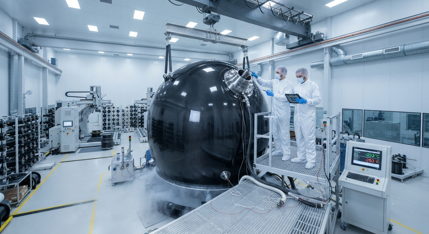
Liquid hydrogen (LH₂) aviation demands CFRP cryogenic tanks at −253 °C. Analysis of Type-IV and Type-V composite tank requirements, material specifications, manufacturing challenges, and market projections to 2035.
Introduction: The Hydrogen Aviation Imperative
The global aviation industry is under unprecedented pressure to decarbonize. In 2025, commercial aviation contributed approximately 2.5% of global CO₂ emissions, a figure projected to reach 4–5% by 2050 without intervention. Hydrogen propulsion — specifically liquid hydrogen (LH₂) burning in modified gas turbines or feeding fuel cells — has emerged as the leading zero-emission pathway for medium- to long-haul aircraft. Central to this technology is the cryogenic hydrogen storage system, and at its core lies the carbon fiber composite tank.
By 2035, industry analysts at McKinsey and Roland Berger project that hydrogen-powered aircraft could enter revenue service on narrow-body routes (150–200 passengers, 2,000–3,500 km range). This timeline places extraordinary demands on carbon fiber tank manufacturers, who must deliver lightweight, fatigue-resistant, cryogenic-pressure vessels at aerospace-grade reliability and commercial-scale cost.
Cryogenic Tank Architecture for LH₂
Liquid hydrogen must be stored at −253 °C (20 K) — just 20 degrees above absolute zero. At this temperature, material selection becomes critical. Aluminum and steel tanks are prohibitively heavy for aviation: a steel Type-I tank would weigh 8–10 times the fuel mass. Carbon fiber reinforced polymer (CFRP) Type-IV and Type-V tanks offer the only viable path.
Type-IV vs Type-V Cryogenic Tanks
| Parameter | Type-IV (Polymer Liner + CF Wrap) | Type-V (Linerless All-CF) |
|---|---|---|
| Operating pressure | 3–10 bar (low-pressure) | 3–10 bar |
| Temperature rating | −253 °C to +80 °C | −253 °C to +80 °C |
| Burst pressure | ≥ 22.5 bar (225% design) | ≥ 22.5 bar |
| Liner material | Polyimide or HDPE (0.3–0.8 mm) | None (integral barrier coating) |
| Weight reduction vs Type-III | 25–30% | 35–40% |
| Cycle life (cryo pressurization) | ~4,500 cycles | ~3,000 cycles (in development) |
| Permeation rate (H₂) | < 10⁻⁵ mbar·L/s·m² | < 10⁻⁴ mbar·L/s·m² |
| Current TRL (2026) | TRL 6 — prototype demo | TRL 4 — lab validated |
| Target unit cost (2035) | $350–450 / kWh storage | $280–380 / kWh storage |
Carbon Fiber Material Requirements
The cryogenic environment imposes unique demands on the composite system. At −253 °C, the epoxy matrix becomes brittle — microcracking from thermal cycling is the primary failure mode. Premium intermediate-modulus (IM) carbon fibers with specific tensile modulus of 290–310 GPa are required to balance stiffness with strain-to-failure. Key specifications include:
- Fiber type: IM7-class (Toray T800S, Hexcel IM7, or equivalent) — 5.5–6.0 GPa tensile strength, 290–300 GPa modulus
- Resin system: Toughened epoxy with −269 °C glass transition (e.g., Solvay CYCOM 5320-1, Hexcel RTM6-2)
- Fiber volume fraction: 60–65% in the hoop direction, 55–60% in helical layers
- Thermal cycling resistance: ≥ 1,000 cycles from −253 °C to +70 °C without microcrack density exceeding 5 cracks/cm²
- Helium leak rate after cycling: ≤ 5 × 10⁻⁶ mbar·L/s
Manufacturing Process Challenges
Filament winding is the established process for cylindrical pressure vessels, but cryogenic aviation tanks introduce three novel challenges:
- Thick-section winding (30–50 mm wall): Conventional wet winding struggles with void content above 2% in sections exceeding 25 mm. Dry fiber placement (DFP) with subsequent resin infusion (VARTM) or automated fiber placement (AFP) with prepregged towpreg are being qualified.
- Boss-to-composite interface: The metallic boss (typically Ti-6Al-4V or Inconel 718) transfers the entire load into the composite dome. The interface must survive thermal contraction mismatch of approximately 0.15–0.20% at cryogenic temperature.
- Vacuum-jacketed integration: The composite tank must be housed within a vacuum insulation shell with a concentricity tolerance of ±2 mm over a 2.5 m length. Multi-layer insulation (MLI) of 40–60 alternating radiation shields is applied between tank and shell.
Market Outlook 2030–2035
| Metric | 2026 (Current) | 2030 (Projected) | 2035 (Target) |
|---|---|---|---|
| Global aviation LH₂ demand (tonnes/day) | < 5 (test rigs) | 50–80 | 800–1,200 |
| Cryogenic tank (CF) units produced/year | ~200 | 1,500–2,000 | 8,000–12,000 |
| Tank weight (kg, for 2.5 t LH₂) | 175–220 | 140–170 | 110–130 |
| Cost per kg of LH₂ stored | $140–180 | $90–120 | $50–70 |
| Carbon fiber content per tank (kg) | 90–110 | 70–90 | 55–70 |
| Global CF demand from aviation (tonnes/year) | ~20 | 140–200 | 600–900 |
Industry Players and Supply Chain Readiness
Leading aerospace composite manufacturers are actively developing cryogenic tank capabilities. Airbus's ZeroE initiative has validated a 5-m-diameter, 35-bar composite tank at TRL 5. Universal Hydrogen (acquired by ZeroAvia in 2025) completed 30+ ground test cycles on a Type-IV 1.8 m tank. In China, COMAC is collaborating with AVIC Composite on a 3-tonne-capacity Type-V demonstrator targeting 2028 completion. Toray Industries announced in February 2026 that its T1200 fiber is being qualified for Airbus's ZEROe cryogenic tank specification.
FAQ — Hydrogen Aviation Composite Tanks
Why can't aluminum or steel be used for aviation LH₂ tanks?
At −253 °C, aluminum 2219 retains acceptable fracture toughness, but the weight penalty is prohibitive. A steel Type-I tank storing 2.5 tonnes of LH₂ would weigh approximately 1,800–2,500 kg — consuming most or all of the aircraft's payload capacity. CFRP Type-IV tanks weigh 175–220 kg for the same capacity, a weight savings of 88–92%. Additionally, steel embrittles severely below −150 °C, requiring expensive nickel-alloy liners. Composite tanks are the only commercially viable path for airborne LH₂ storage.
What is the expected service life of a CFRP cryogenic tank?
Based on current Airbus and Boeing fatigue test programs, a Type-IV tank with toughened epoxy system is expected to achieve 8,000–12,000 flight cycles (takeoff-to-landing pressurization cycles) before retirement, corresponding to approximately 15–20 years of service for narrow-body aircraft. The limiting factor is microcrack accumulation in the matrix, which gradually increases hydrogen permeation. Nondestructive inspection (ultrasonic C-scan and acoustic emission) at every C-check (5,000 cycles) is anticipated.
Which carbon fiber grade is best suited for cryogenic LH₂ tanks?
The optimal balance today is an intermediate-modulus fiber in the 290–310 GPa range with tensile strength of 5.5–6.0 GPa — specifically Toray T800S (6.0 GPa/294 GPa), Hexcel IM7 (5.7 GPa/303 GPa), or Mitsubishi MR70 (5.8 GPa/295 GPa). Higher-modulus fibers (M55J, 540 GPa) have insufficient strain-to-failure (0.5% vs. 1.8% for T800S) and crack under cryogenic thermal stress. The fiber-matrix interface must be sized specifically for cryogenic service — standard aerospace sizings optimized for 120 °C cure cycles delaminate at −253 °C.
How close is the industry to serial production of aviation LH₂ tanks?
Airbus has publicly targeted 2028 for a first flight of a hydrogen-powered A320-sized testbed, with entry into revenue service targeted for 2035. COMAC follows a similar timeline. The bottleneck today is not tank manufacturing capability (filament winding is mature) but certification — no civil aviation authority has yet certified a CFRP cryogenic pressure vessel for passenger flight. EASA and FAA are developing dedicated composite-cryogenic certification frameworks, expected by 2029–2030. Serial production capacity will need to scale from today's ~200 units/year to 8,000–12,000 units/year by 2035 — a 40–60× scale-up that will strain the global aerospace-grade carbon fiber supply.
Part of topic
Related Articles
- Recycled Carbon Fiber Market Forecast 2030: Technology Maturity and Commercialization Path
- South Korea Carbon Fiber Market 2026: Hydrogen Economy and Shipbuilding Innovation
- Wind Turbine Blade Leading Edge Protection 2026: Polyurethane, Tape, and Metallic Shield Solutions
- China Carbon Fiber Overcapacity 2026: Price War Impact and Industry Consolidation
- India Carbon Fiber Market 2026: Wind Energy, Aerospace, and Defense Expansion
- PAN Precursor Market 2026: Acrylonitrile Supply and Carbon Fiber Cost Structure
Interested in Our Products?
Contact our team for competitive pricing and technical specifications.
Get a QuoteRelated Products

Custom Carbon Fiber Medical Device Components
Medical-grade carbon fiber components manufactured for imaging equipment, surgical instruments, and patient support systems. Carbon fiber's radiolucency (X-ray transparency) and high strength-to-weight ratio make it ideal for CT scanner beds, wheelchair frames, surgical robot arms, and MRI-compatible accessories. Biocompatible resin systems available.

Carbon fiber standard plate-3k stripe
Lightweight, ultra-rigid standard sheets for drone fuselages, robot housings, facades and structural applications.

Square Carbon Fiber Tube — 3K Twill T700
Square cross-section carbon fiber tube manufactured with 3K twill weave for torsional strength. Preferred for structural frames, trusses, and support columns where rectangular geometry offers design flexibility.

Carbon Fiber Plate — 3K Twill T700 3.0mm
Medium-thickness 3.0mm carbon fiber plate offering significantly higher load capacity while maintaining attractive 3K twill finish. Suitable for structural brackets, reinforcement plates, and load-bearing panels.

Carbon Fiber Plate — 3K Twill T700 1.5mm
Thin 1.5mm carbon fiber plate with 3K twill weave surface. Lightweight and stiff, commonly used for covers, panels, drone bodies, and applications requiring a premium aesthetic appearance.