
Hydrofoils have transformed both ends of the marine market. At the performance end, the International Moth singlehanded dinghy foils at more than 25 knots, and America's Cup AC75 yachts accelerate past 50 knots on foils that lift the entire hull clear of the water. At the commercial end
Introduction
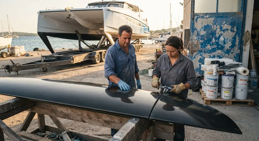
Hydrofoils have transformed both ends of the marine market. At the performance end, the International Moth singlehanded dinghy foils at more than 25 knots, and America's Cup AC75 yachts accelerate past 50 knots on foils that lift the entire hull clear of the water. At the commercial end, electric foiling ferries such as the Candela P-12 and the Navier N-30 cruise above 25 knots while consuming a fraction of the energy of a conventional planing hull. Carbon fiber is the thread connecting all of these: every modern foil — strut, wing, and control surface — is built from carbon fiber composites because no other material delivers the combination of stiffness, strength, and weight that flying hulls demand.
This article explains how foil lifting surfaces generate lift, reviews the load cases that dominate hydrofoil structural design, and details the material and manufacturing choices that make carbon fiber foils reliable in seawater.
How a Foil Lifts a Hull
A hydrofoil works exactly like an aircraft wing, but in water. The foil generates lift proportional to the square of boat speed, the foil area, and the lift coefficient: lift equals one half times water density times the square of velocity times planform area times lift coefficient. Below the takeoff speed the hull remains waterborne, and as speed rises the foil produces enough lift to carry the vessel weight, the hull rises clear of the water, and drag collapses because wetted surface shrinks dramatically.
Foil-borne operation changes the loading picture completely. The hull no longer absorbs wave impacts — the foil system does, and it transmits those loads to the hull through the strut attachments. Designers therefore size foils not for the pleasant steady-state cruise, but for the transient loads of waves, slams, and speed transitions.
| Vessel Type | Typical Cruise Speed | Foil Arrangement | Dominant Loads |
|---|---|---|---|
| International Moth dinghy | 18-25 knots | Single main foil plus T-foil rudder | Crew-induced control loads, wave slams |
| AC75 racing yacht | 35-50 knots | Twin canting foils with flaps, VLM | Ventilated lift, violent slamming, steering loads |
| Foiling electric ferry | 25-30 knots | Two forward C-foils and one aft foil | Regular wave fatigue, passenger-weight cycles |
| Foiling multihull ferry | 30-40 knots | L-foils or V-foils on each hull | Continuous high-speed wave impacts |
Load Cases That Drive Foil Design
Four load cases dominate the structural design of carbon fiber hydrofoils, and each leaves a fingerprint in the laminate.
- Steady foil-borne lift: The foil carries the vessel weight minus residual hull lift, distributed along the wing span. This is the baseline case, and it sets the high-stiffness requirement that favors high-modulus carbon fiber.
- Slamming and wave impacts: When a foil pierces a wave crest at speed, the transient pressure spike can reach several times the steady lift. Racing foils are designed against slams at high angles of incidence; ferry foils against repeated moderate slams in coastal chop.
- Cavitation and ventilation: Low-pressure regions on the upper foil surface can trigger cavitation — vapor bubbles that collapse violently — and ventilation, where air is drawn down from the surface and detaches the lifting flow. Both cause unsteady load oscillations and local erosion of the foil surface.
- Fatigue: A ferry foil accumulates millions of wave-load cycles over its life, so the laminate must be designed for fatigue at realistic amplitude distributions, not just ultimate strength. Racing foils, in contrast, are fatigue-limited by a few thousand hard racing hours.
Grounding and debris impact are the wildcard case. Foils strike logs, containers, and shallow seabeds, so the lower wingtips are typically strengthened with local impact-resistant layups and replaceable tips that are cheaper to swap than to repair.
Foil Architecture: Struts, Wings, and Control Surfaces
Most carbon fiber foils are built on the strut-plus-wing pattern. The strut carries the vertical load and provides the arm that balances the vessel's righting moment, while the wing generates the horizontal lift that lifts the hull. Sailboats favor T-foils, where the wing is perpendicular to the strut, and L-foils, where the wing sweeps toward the rear; both solve the righting-moment problem without excessive strut length. Large ferries use two forward C-foils and a single aft foil, with each foil angle-adjusted in real time by a control computer that holds the hull level in waves.
America's Cup AC75 yachts pushed the architecture furthest with vertical-lift foils that ventilate deliberately — the so-called vertical lift mode — trading some lift for dramatically lower drag at extreme speed. The carbon fiber construction is the same family as ferry foils but optimized for stiffness-to-weight and impact tolerance against slams at 50 knots.
Materials and Construction in Seawater
Foils are built almost exclusively from unidirectional carbon fiber in a sandwich construction: high-modulus fiber where stiffness governs the spanwise bending, intermediate-modulus fiber such as T700 and T800 where toughness and impact resistance matter, and a foam or balsa core between carbon skins to stabilize the thin airfoil sections against buckling and local denting.
Seawater adds three complications that land-based composites never face:
- Galvanic isolation: Carbon fiber is electrochemically noble relative to aluminum and stainless steel, so any contact between carbon structure and metal fittings in seawater drives rapid galvanic corrosion of the metal. Isolation layers of glass fiber laminate, insulated fasteners, and sacrificial protection are mandatory at every interface.
- Water ingress: Epoxy systems absorb small amounts of moisture, which softens the matrix over time. Foils use marine-grade epoxy, sealed edges, and drained cores to keep absorbed water out of the sandwich.
- Leading edge erosion: High-speed water flow and entrained sand erode the leading edges. Protective coatings and replaceable leading edge caps extend service life before the load-bearing laminate is exposed.
Manufacturing follows established composite practice: CNC-machined foam cores, automated or hand layup of unidirectional prepreg, and curing in autoclave or a robust out-of-autoclave cycle. Large foil wings for ferries are increasingly made with resin infusion, which lowers cost for bigger parts while holding fiber quality.
Frequently Asked Questions
Why is carbon fiber the standard material for hydrofoils?
Foil wings are slender cantilevers subject to fatigue, slamming, and hydrodynamic loads, and they must stay stiff under those loads to maintain lift performance. Carbon fiber offers the highest stiffness-to-weight and strength-to-weight ratios of any structural material, so foil builders can achieve the required stiffness with thin, low-drag sections. Aluminum foils are heavier and suffer seawater corrosion, while steel is far too heavy for foiling vessels.
What is the difference between a T-foil and an L-foil?
A T-foil mounts the wing at right angles to the strut, which is simple and structurally efficient, and it is the classic arrangement on dinghies and small performance boats. An L-foil angles the wing toward the rear so the strut meets the wing at a smooth transition, reducing tip vortex drag and providing a more gradual load path. Both are carbon fiber laminate structures; the choice is driven by the vessel's stability, speed range, and control strategy.
How do foiling ferries handle waves?
Ferry control systems continuously adjust foil angles to keep the hull level, using ride-height sensors and gyroscopes reading wave motion ahead. The foils absorb the majority of wave energy before it reaches the hull, which is why foiling ferries have dramatically lower motion sickness rates than conventional vessels. The structural consequence is that ferry foils are designed for millions of moderate wave-load cycles — a pure fatigue design case.
Can carbon fiber foils be repaired after grounding or impact?
Yes, most foil damage is repairable. Crashes typically dent or crack the lower wingtip, and many foils are built with replaceable tip sections that are swapped rather than repaired. Deeper structural damage is repaired with the same wet layup and vacuum-bag procedures used across the composites industry, followed by ultrasonic inspection and re-balance of the foil set. Shops should keep spare tips and a documented repair procedure for foil-holding vessels.
Conclusion
Carbon fiber hydrofoils have converted wave-riding hulls into flying hulls across racing sailboats, performance dinghies, and commercial passenger ferries. The lifting surfaces must carry steady foil-borne loads, survive slamming spikes several times that level, manage cavitation and ventilation, and tolerate millions of fatigue cycles in seawater — a combination of requirements only carbon fiber composite construction satisfies in a practical weight budget. For naval architects and boat builders, specifying the right fiber grade, sandwich core, and galvanic isolation detail is the difference between a foil that flies for decades and one that returns to the shop every season.
Browse YongXian's carbon fiber materials for hydrofoil construction, or contact our engineering team for high-modulus tow grades, prepreg vouchers, and supply programs for marine composite builders.
Related Articles
Interested in Our Products?
Contact our team for competitive pricing and technical specifications.
Get a QuoteRelated Products

Carbon Fiber Plate — 3K Twill T700 3.0mm
Medium-thickness 3.0mm carbon fiber plate offering significantly higher load capacity while maintaining attractive 3K twill finish. Suitable for structural brackets, reinforcement plates, and load-bearing panels.

Carbon Fiber Plate — 3K Twill T700 1.5mm
Thin 1.5mm carbon fiber plate with 3K twill weave surface. Lightweight and stiff, commonly used for covers, panels, drone bodies, and applications requiring a premium aesthetic appearance.

Square Carbon Fiber Tube — 3K Twill T700
Square cross-section carbon fiber tube manufactured with 3K twill weave for torsional strength. Preferred for structural frames, trusses, and support columns where rectangular geometry offers design flexibility.

Carbon Fiber Plate — UD Unidirectional T700
Unidirectional carbon fiber plate with all fibers oriented in a single direction for maximum strength along the fiber axis. Essential for structural reinforcements, splints, and applications where load direction is predictable.

Round Carbon Fiber Tube — UD Unidirectional T700
Unidirectional (UD) round tube with all fibers aligned axially for maximum longitudinal stiffness. Ideal for applications requiring high bending rigidity with minimal weight, such as shafts, struts, and structural reinforcements.