
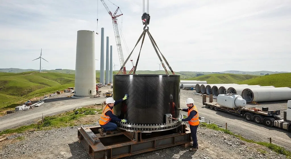
Wind speed increases with height, and the energy in wind scales with the cube of its speed — which is why every turbine manufacturer is chasing taller towers. A tower that reaches from 100 m to 160 m hub height accesses a stronger, steadier wind regime that can raise annual energy produ
Introduction
Wind speed increases with height, and the energy in wind scales with the cube of its speed — which is why every turbine manufacturer is chasing taller towers. A tower that reaches from 100 m to 160 m hub height accesses a stronger, steadier wind regime that can raise annual energy production by 10-20% on the same site. But tall towers run into two hard constraints: road transport limits on segment size, and the structural penalty of supporting a heavy nacelle on an increasingly tall and heavy column.
Hybrid towers resolve the transport problem directly. The lower portion of the tower is built from concrete segments — cast on site or nearby, so transport size is not a constraint — while the upper portion remains conventional steel, and a transition piece joins the two materials. This article explains how hybrid wind tower segments work, the structural role of the transition piece, and why carbon fiber is entering tower design at the transition and beyond.
The Transport Constraint and the Hybrid Answer
Steel tower segments are limited by the width and length of road-legal loads. A typical truck permits a segment diameter around 4.2-4.5 m and lengths up to 30 m, which constrains tower base diameter to roughly 4.5 m for a conventional steel tower. Since tower stiffness scales with the fourth power of diameter, this diameter ceiling is a hard structural limit: a 4.5 m base simply cannot carry the bending moments of a 160 m tower without excessive wall thickness and weight. Concrete breaks the ceiling because it is cast in place or in local plants, so the base diameter can grow to 6-8 m or more.
The hybrid tower therefore optimizes by material: concrete at the base where the bending moments are highest and mass matters least relative to the ground, steel in the upper sections where mass and transport efficiency matter most, and a transition piece at the junction. Commercial hybrid towers have reached 160-180 m hub heights in service, with the concrete base typically extending to 60-100 m and the steel top carrying the nacelle.
What the Transition Piece Does
The transition piece — the structural element that transfers load from the concrete base to the steel upper tower — is the most demanding part of the hybrid tower. It must reconcile two materials with different stiffness, different thermal expansion, and different construction tolerances, while carrying the full tower bending moment and distributing it into the concrete without local crushing. A poorly designed transition concentrates stress and drives fatigue damage at the junction, so its design governs the reliability of the whole tower.
Two configurations dominate. In the ring solution, a steel ring is embedded in the top of the concrete section, with anchor bolts or grouted connections transferring load to the steel tower above. In the overlap solution, the steel section extends down into the concrete section, with the interface secured by shear studs and grout. Both must manage the stiffness jump: the sudden change in bending stiffness between concrete and steel creates a stress concentration that fatigue analysis must address over the 25-30 year design life, typically at 10 million or more load cycles.
Carbon fiber enters the picture here in two ways. First, composite transition segments can smooth the stiffness gradient: by tapering a CFRP-steel hybrid segment, designers spread the load transition over a length rather than concentrating it at a ring. Second, CFRP's corrosion immunity matters at the junction, where moisture collecting at the concrete-steel interface is a known corrosion risk — the transition is the one place in the tower where water and steel reliably meet. A composite transition segment eliminates this failure mode at its source.
Carbon Fiber in the Upper Tower
The upper tower sections carry a different logic. Near the nacelle, the tower cross-section is small and the bending moment is reduced, but the top sections carry the concentrated mass of the rotor and nacelle — typically 250-400 tonnes for a 15-16 MW class turbine. Every kilogram of tower mass above a certain height must be lifted, positioned, and supported, so weight reduction in the upper sections compounds: lighter top sections reduce the load on every lower section and on the foundation.
Carbon fiber hybrid sections — steel flanges or shells combined with CFRP panels, or pure CFRP tower segments — cut upper-tower mass substantially. Steel tower wall thickness near the top is driven by local buckling and by the connection flanges; carbon fiber's higher specific stiffness and strength allow thinner, lighter sections at equal buckling resistance. Studies of hybrid steel-carbon tower tops report mass savings in the upper sections on the order of 30-50% versus all-steel, with the greatest benefit on the tallest towers where the top sections are longest.
The practical near-term application is selective: carbon fiber in the transition piece and in the uppermost flange and connection zones, where its fatigue and corrosion properties and its mass advantage deliver the highest value. As carbon fiber pricing falls and high-volume wind-grade material becomes available, the composite share of tower structure is expected to grow from transition details toward full hybrid segment production.
Comparison: Tower Configurations
| Parameter | All-Steel Tower | Concrete-Steel Hybrid | Hybrid with CFRP Transition / Top |
|---|---|---|---|
| Maximum practical hub height | ~120-140 m | 160-180 m | 180 m+ |
| Base diameter limit | ~4.2-4.5 m (transport) | 6-8 m (cast on site) | 6-8 m |
| Transport constraint on base | Hard limit | None (in-situ casting) | None |
| Upper-section mass (index) | 1.0 | 0.9-1.0 | 0.6-0.7 |
| Corrosion risk at material junction | N/A | Moderate (steel-concrete interface) | Low (composite transition) |
| Foundation load (index) | 1.0 | 1.05-1.15 | 0.95-1.05 |
| Site logistics complexity | Low (truck segments) | High (casting plant) | High plus CFRP supply chain |
| Capital cost (tower, index) | 1.0 | 0.9-1.2 | 1.1-1.4 |
| Typical application | Onshore, <140 m | Onshore tall towers | Tall towers, complex sites |
The comparison shows the hybrid tower's role: it is the configuration that unlocks hub heights beyond the transport ceiling, and the carbon fiber transition piece is the detail that makes the junction reliable over the tower's 25-30 year fatigue life. The cost premium of composite elements is justified where taller towers access a stronger wind regime — typically a 10-20% energy gain that repays the tower investment over the project lifetime.
Logistics and Site Considerations
- Concrete segment casting: The concrete base is cast in segments on site or in a local plant, with segment weights of 50-120 tonnes handled by the same cranes that erect the tower. In-situ casting eliminates the transport constraint on base diameter entirely.
- Steel section transport: The upper steel sections are transported as road-legal loads — typically 20-30 m segments with a diameter under 4.5 m — to the site, where they are stacked and bolted.
- Transition piece installation: The transition piece is lifted into position after the concrete tower is complete, aligned, and secured with grouted or bolted connections. CFRP transition segments are lighter than steel equivalents, easing the critical lift at the tower top.
- Assembly sequence: The concrete base is erected first, followed by the transition piece, then the steel sections and nacelle. The sequence is crane-limited, so segment mass at every step must fit the chosen installation crane.
- On-site quality control: Grout pours at the transition, bolt torqueing, and CFRP segment handling all follow documented procedures, with non-destructive inspection of the junction completed before the tower is loaded.
Site logistics drive the economic case for hybrid towers.
Frequently Asked Questions
Why can't steel towers simply be made taller without changing materials?
Steel towers are constrained by the road transport limit on segment diameter, roughly 4.2-4.5 m. Since tower stiffness scales with the fourth power of diameter, a steel tower base cannot grow beyond this ceiling, so taller all-steel towers must rely on increased wall thickness and weight — which raises material, transport, and foundation costs to the point of diminishing returns above roughly 140 m hub height. The hybrid tower escapes the ceiling by casting the concrete base on site, where no transport limit applies, making 160-180 m towers practical.
What makes the transition piece the critical part of a hybrid tower?
The transition piece transfers the full tower bending moment between concrete and steel — two materials with different stiffness, thermal expansion, and tolerance — while distributing the load into the concrete without crushing it. The sudden stiffness change at the junction creates a stress concentration that drives fatigue damage over the tower's 25-30 year life, and the concrete-steel interface is a known corrosion risk where water collects. A well-designed transition manages both fatigue and corrosion, which is why its quality governs the reliability of the entire tower.
How much energy gain justifies the higher cost of a taller hybrid tower?
Wind energy scales with the cube of wind speed, and the stronger, steadier wind at 160 m hub height compared with 120 m typically increases annual energy production by 10-20% on the same site. For a 15 MW turbine operating at a good wind site, that gain can represent several gigawatt-hours per year, worth far more than the tower cost premium over the project lifetime. The hybrid tower and its carbon fiber elements pay back through this energy uplift, with the economic case strongest on sites with the strongest vertical wind gradient.
Conclusion
Hybrid wind towers answer the transport ceiling with a material change: concrete bases cast on site, steel upper sections transported conventionally, and a transition piece that reconciles the two. Carbon fiber strengthens the concept at its most vulnerable detail — the junction — by smoothing the stiffness gradient, eliminating corrosion at the interface, and cutting mass in the upper tower sections where weight compounds. The result is a practical route to 160-180 m hub heights and the 10-20% energy gain they deliver.
For B2B buyers in the wind energy industry, the key specification criteria are transition piece fatigue life, corrosion performance at the junction, and upper-tower mass savings. Explore our carbon fiber laminate and profile range suited to transition piece and tower applications, or contact our engineering team for material selection guidance and structural support for your tower program.
Related Articles
- Carbon Fiber Sheets for Sale: A Buyer Checklist for Thickness, Weave and Finish
- Carbon Fiber Plate Running Shoes: Manufacturing Process and Material Specifications
- Carbon Fiber Tubes for Sale: Spec Sheet Fields That Actually Matter
- Carbon Fiber Sheets Near Me: Local Dealers and Quick Turnaround Procurement
- Carbon Fiber Tubes Near Me: Local Stock Availability and Same-Day Delivery Options
- Carbon Fiber Plate Orthotic: Lightweight Prosthetic and Medical Device Applications
Interested in Our Products?
Contact our team for competitive pricing and technical specifications.
Get a QuoteRelated Products

Carbon Fiber Plate — 3K Twill T700 1.5mm
Thin 1.5mm carbon fiber plate with 3K twill weave surface. Lightweight and stiff, commonly used for covers, panels, drone bodies, and applications requiring a premium aesthetic appearance.

Carbon Fiber Plate — 3K Twill T700 3.0mm
Medium-thickness 3.0mm carbon fiber plate offering significantly higher load capacity while maintaining attractive 3K twill finish. Suitable for structural brackets, reinforcement plates, and load-bearing panels.

Square Carbon Fiber Tube — 3K Twill T700
Square cross-section carbon fiber tube manufactured with 3K twill weave for torsional strength. Preferred for structural frames, trusses, and support columns where rectangular geometry offers design flexibility.

Carbon Fiber Plate — UD Unidirectional T700
Unidirectional carbon fiber plate with all fibers oriented in a single direction for maximum strength along the fiber axis. Essential for structural reinforcements, splints, and applications where load direction is predictable.

Round Carbon Fiber Tube — UD Unidirectional T700
Unidirectional (UD) round tube with all fibers aligned axially for maximum longitudinal stiffness. Ideal for applications requiring high bending rigidity with minimal weight, such as shafts, struts, and structural reinforcements.