
In aerospace assembly, carbon fiber parts are rarely finished when they leave the autoclave. They must be drilled, countersunk, and bolted together to form wings, fuselage panels, and control surfaces — and every drilled hole is a potential defect site. Delamination, the separation of p
Introduction
In aerospace assembly, carbon fiber parts are rarely finished when they leave the autoclave. They must be drilled, countersunk, and bolted together to form wings, fuselage panels, and control surfaces — and every drilled hole is a potential defect site. Delamination, the separation of plies at the hole edge, is consistently reported as the most common damage type found in drilled CFRP components, ahead of fiber pullout, matrix cracking, and hole-edge fraying. Because a delaminated hole can grow under fatigue load into a structural failure, aerospace standards treat delamination as a reject-level defect, and the entire drilling process is engineered to prevent it.
Preventing delamination is not a matter of buying a better drill. It requires understanding how the cutting tool, the feed rate, and the support around the exit side interact, and then locking those parameters into a controlled production process. This article covers the mechanics of delamination, the drill geometries that resist it, the role of feed and thrust force, and the CNC drilling series that makes hole quality repeatable across hundreds of fastener locations.
Why Carbon Fiber Delaminates During Drilling
Carbon fiber laminates are strong in-plane but weak through the thickness, and drilling exploits that weakness twice. At the drill entry, the cutting edges push down on the plies as they shear, bending the outermost ply inward and producing a "peel-up" delamination ring around the hole mouth. At the exit, the drill tip pushes against the last plies, which are no longer backed by material beneath them; when the thrust force exceeds the interlaminar strength of the remaining plies, they separate and form the more serious "push-out" delamination, a cone-shaped crack that can extend several times the hole diameter.
Three factors control this damage:
- Thrust force: the axial force of the drill pushing into the laminate. Delamination at the exit initiates when thrust exceeds a critical threshold that depends on laminate thickness and interlaminar fracture toughness.
- Exit-side support: backing material that keeps the last plies from bending away from the drill. Unsupported drilling produces the largest delamination zones.
- Tool sharpness and geometry: sharp edges cut rather than crush fibers, and a well-designed point spreads the cutting action so less force is required.
Of these, thrust force at exit is the parameter most directly correlated with delamination size — which is why feed rate, the main controller of thrust, receives so much attention in composite drilling literature.
Drill Bit Geometry for CFRP
Standard twist drills, designed for metal, are the wrong tool for carbon fiber. Their geometry tends to produce high thrust and poor hole quality in composites. Dedicated CFRP drills use a modified point design and often a wear-resistant coating.
The table below summarizes the drill families used in aerospace CFRP assembly:
| Drill type | Geometry | Key benefit | Typical use |
|---|---|---|---|
| Standard twist drill | 118° point, straight flutes | Low cost, universal | Non-critical, low-volume drilling |
| Double-point-angle drill | Primary and secondary point angles | Reduced thrust and entry burr | General CFRP drilling, thinner laminates |
| Brad-and-spur / dagger drill | Sharp periphery cutting edge | Clean fiber cut at hole rim | Precision holes, skin panels |
| Diamond-coated drill | Multi-facet point + CVD diamond | Long tool life, low wear over hundreds of holes | Production series in CFRP stacks |
| Step drill | Two diameters in one tool | Drills and reams in a single operation | High-volume fastener holes |
The double-point-angle geometry is the workhorse of aerospace CFRP drilling. A larger primary point angle reduces the effective thrust force by splitting the cutting action between the point and the secondary edge, and it lowers the chance of fiber breakout at the hole edge. For production runs, the diamond coating matters as much as the geometry: an uncoated carbide drill in carbon fiber wears quickly because the abrasive fibers blunt the cutting edge, and a worn drill pushes instead of cutting, raising thrust and triggering delamination on the very next holes.
Feed Rate and Thrust Force Control
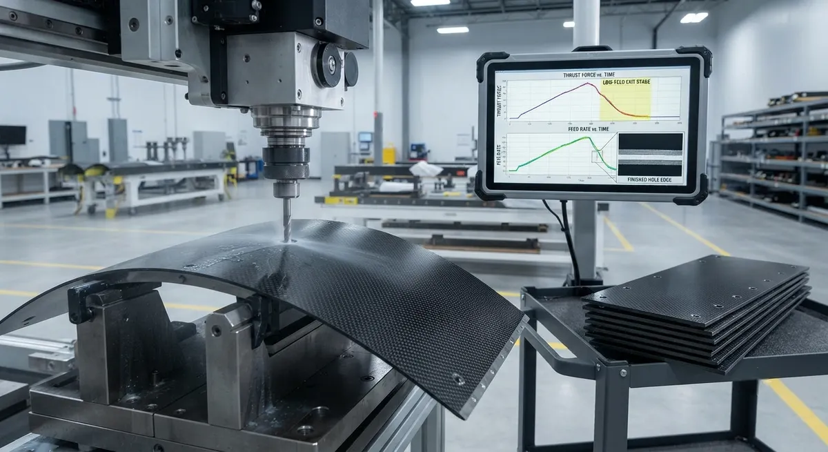
Feed rate is the primary lever on delamination. Because thrust force rises with feed rate, the standard practice is to drill the laminate with a low feed at the exit stage: the last 1-2 millimeters of the cut are performed at a reduced feed — often 0.01-0.03 mm/rev against 0.05-0.10 mm/rev for the bulk of the hole — so the thrust stays below the critical threshold of the remaining plies.
- Peck drilling: retracting the drill at intervals clears chips and reduces heat buildup, but must be used with care because repeated re-entry can abrade the hole wall.
- Spindle speed: higher speeds generally improve hole quality within the thermal limit; excessive speed overheats the matrix and causes resin softening and smearing.
- One-shot drilling: a single continuous pass with feed reduction at exit, the preferred approach for automated production because it avoids the re-entry damage of pecking.
In automated cells, thrust force is sometimes monitored in real time with a load cell or spindle current sensing, and the feed is dropped automatically when the drill approaches the exit. This closes the loop between tool condition and hole quality: as the drill wears and thrust creeps upward, the system compensates before a delamination occurs.
Exit-Side Support: The Back-Up That Saves the Last Plies
Exit-side support is the single most effective mechanical defense against push-out delamination. A backing plate, sacrificial backup, or a supporting anvil under the exit face keeps the final plies from flexing away from the drill, so the thrust force is resisted locally and the critical threshold for delamination rises substantially. Studies of supported versus unsupported drilling in CFRP routinely show that a rigid backup reduces delamination factor — the ratio of maximum damage diameter to hole diameter — from values above 1.5 down to below 1.2.
Three support strategies are common in aerospace assembly:
- Sacrificial backup plates: thin aluminum or phenolic panels placed under the laminate. They are drilled through along with the part and discarded, giving full support and a clean exit burr.
- Back-drilling with two-sided access: both faces of the panel are accessible, allowing a second drill or a manual drill bushing to enter from the opposite side.
- Monolithic support tooling: drill jigs and assembly fixtures with hardened steel bushings that locate the hole and back the laminate at the same time, used on wing skins and fuselage frames.
Where no backup is possible, the feed-rate reduction at exit becomes the only defense, which is why exit-side feed control and support are always specified together in production drilling procedures.
The CNC Drilling Series for Production
Hand drilling in carbon fiber is inherently variable, which is why production aerospace assembly has moved to CNC drilling series on dedicated machines or robotic end-effectors. A typical CNC sequence for a fastener hole runs through four stages:
- Stage 1 — Clamping and location: the panel is held rigidly and the hole position is confirmed against the drill template or laser-projected grid; any vibration or part movement at this stage ruins the hole.
- Stage 2 — Drill entry: the spindle approaches at a reduced entry feed with coolant or mist, cutting the peel-up-prone outer plies cleanly.
- Stage 3 — Main feed: the drill advances at normal feed through the laminate body, with continuous coolant to protect the resin matrix.
- Stage 4 — Exit management: feed drops to the low exit value for the final millimeters, then the tool retracts and the hole is inspected by a vision system or automatic probe for delamination and diameter.
A well-run CNC series achieves delamination factors below 1.1 across thousands of holes, with tool changes scheduled by hole count or thrust monitoring rather than by inspection failures. The same series logic applies whether the machine is a five-axis gantry driller on a wing skin or a robot cell drilling fuselage splices.
Frequently Asked Questions
Why is delamination the most common defect in CFRP drilling?
Carbon fiber laminates are strong in-plane but weak in the thickness direction, where only the polymer matrix and interlaminar toughness hold the plies together. The drilling process generates high axial thrust, and at the drill exit the last plies are unsupported and bend away, so the interlaminar bond fails locally. No other machining operation creates such a combination of localized force and weak material direction, which is why delamination appears more often than any other CFRP hole defect.
What feed rate should be used when drilling carbon fiber?
Bulk drilling typically runs at 0.05-0.10 mm/rev with spindle speeds of 3000-6000 rpm depending on tool diameter and laminate thickness. The critical parameter is the final stage: the last 1-2 mm before breakthrough should be drilled at a reduced feed of 0.01-0.03 mm/rev to keep thrust below the delamination threshold. Higher feeds at exit increase the delamination factor measurably, so the exit feed matters more than the bulk feed.
Do diamond-coated drills really help with CFRP?
Yes. Carbon fiber is highly abrasive, and an uncoated carbide drill loses its edge within a few hundred holes, after which the worn tool pushes fibers aside instead of cutting them, raising thrust and causing delamination. A CVD diamond-coated drill maintains a sharp edge for thousands of holes, keeping thrust low and hole quality consistent. The coating does not change the cutting mechanics, but it preserves the geometry that does.
Is exit-side support always necessary for composite drilling?
For structural aerospace holes, exit-side support is strongly recommended and usually required by process specifications. A sacrificial backup plate or drill jig backing can reduce the delamination factor from above 1.5 to below 1.2 because it prevents the final plies from flexing. Where access makes support impossible, the exit feed must be reduced sharply, and the process must be validated with test coupons to confirm the delamination factor stays within limits.
Conclusion
Delamination is not an unavoidable cost of drilling carbon fiber — it is the predictable result of uncontrolled thrust at an unsupported exit face. By pairing a CFRP-specific drill geometry with a controlled feed profile and rigid exit-side support, aerospace manufacturers convert the most defect-prone operation in composite assembly into a process that produces thousands of consistent holes. Diamond-coated, double-point-angle drills run in a disciplined CNC series are the practical answer, with tool condition monitored so a worn edge is replaced before it damages a single part.
Material consistency plays a supporting role: a laminate built from predictable, uniform prepreg drills more repeatably than one with variable fiber volume and resin content. Explore our carbon fiber fabrics and prepreg materials with consistent batch documentation, or contact our engineering team to discuss material specifications for your composite assembly program.
Part of topic
Related Articles
- Carbon Fiber Drone Blades and Propellers: Stiffness, Balance and Noise Reduction
- Fiberglass Filament Wound Tubes: Cost-Effective Alternative to Carbon Fiber
- Filament Wound Epoxy Tube Design: Wall Thickness, Fiber Angle and Load Optimization
- Filament Wound Epoxy Tubes: Testing Standards and Quality Assurance
- Filament Wound Epoxy Tubes Manufacturing: Process and Quality Control
- Filament Wound Fiberglass Tube: Process Parameters and Performance vs Carbon Fiber
Interested in Our Products?
Contact our team for competitive pricing and technical specifications.
Get a QuoteRelated Products

Carbon fiber standard plate-3k stripe
Lightweight, ultra-rigid standard sheets for drone fuselages, robot housings, facades and structural applications.

Carbon Fiber Plate — 3K Twill T700 3.0mm
Medium-thickness 3.0mm carbon fiber plate offering significantly higher load capacity while maintaining attractive 3K twill finish. Suitable for structural brackets, reinforcement plates, and load-bearing panels.

Carbon Fiber Plate — 3K Twill T700 1.5mm
Thin 1.5mm carbon fiber plate with 3K twill weave surface. Lightweight and stiff, commonly used for covers, panels, drone bodies, and applications requiring a premium aesthetic appearance.

Custom Carbon Fiber Medical Device Components
Medical-grade carbon fiber components manufactured for imaging equipment, surgical instruments, and patient support systems. Carbon fiber's radiolucency (X-ray transparency) and high strength-to-weight ratio make it ideal for CT scanner beds, wheelchair frames, surgical robot arms, and MRI-compatible accessories. Biocompatible resin systems available.

Square Carbon Fiber Tube — 3K Twill T700
Square cross-section carbon fiber tube manufactured with 3K twill weave for torsional strength. Preferred for structural frames, trusses, and support columns where rectangular geometry offers design flexibility.