
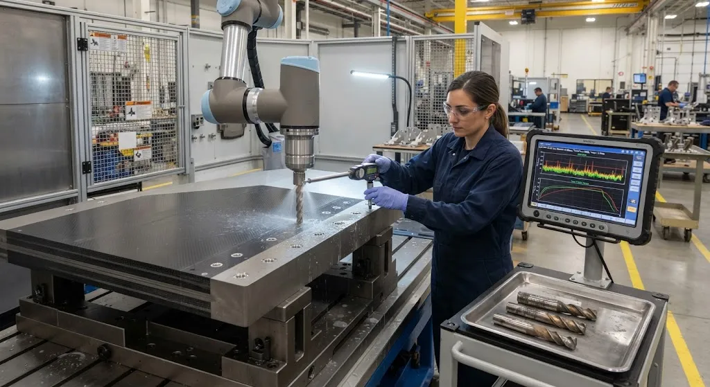
Assembling a modern aircraft wing or fuselage means drilling hundreds of thousands of holes through stacked CFRP and titanium layers, typically Ti-6Al-4V against a carbon fiber laminate. The operation sounds simple, but it confronts the machinist with a contradiction: titanium is tough
Introduction
Assembling a modern aircraft wing or fuselage means drilling hundreds of thousands of holes through stacked CFRP and titanium layers, typically Ti-6Al-4V against a carbon fiber laminate. The operation sounds simple, but it confronts the machinist with a contradiction: titanium is tough and generates intense heat that rapidly wears the cutting edge, while CFRP is brittle and delaminates at the hole exit when the drill breaks through. Improving one outcome usually worsens the other.
The solution is the one-shot stack drill — a tool and a parameter set engineered so that a single pass produces a fastener-ready hole with acceptable surface finish, bore accuracy, and exit quality in both materials. This article examines the wear mechanisms, the delamination physics, and the process variables that determine whether a stack drill lasts its rated life and whether the holes it produces pass inspection.
Why Stacks Are Hard: Two Materials, Opposite Failure Modes
CFRP and titanium sit at opposite ends of the machinability spectrum. Titanium is a heat sink that conducts poorly, so cutting energy stays near the tool edge; its chips weld to carbide, promoting edge chipping and rapid flank wear. CFRP is abrasive — the hard carbon fibers blunt the cutting edge — yet soft in the matrix, so excessive feed force pushes uncut fibers outward at the exit, creating delamination and fiber pullout. The same drill that survives titanium can tear the CFRP exit, and the speeds that protect the CFRP can glaze the titanium.
The table below summarizes the competing constraints the process engineer must balance:
| Material | Dominant Wear Mode | Heat Behavior | Key Defect | Preferred Cutting |
|---|---|---|---|---|
| CFRP layer | Abrasive edge rounding | Low conductivity, epoxy softening | Exit delamination, fiber pullout | High speed, low feed |
| Ti-6Al-4V layer | Adhesion, chipping, flank wear | Intense heat at cutting edge | Built-up edge, bore burn | Low speed, high feed |
| Stack (CFRP over Ti) | Combined, fastest at interface | Heat accumulates across holes | Fretting at interface, exit burr | Compromise mid-range |
The practical resolution is a stepped or customized drill geometry with a moderate speed and controlled feed, run under peck or orbital strategies that manage the two regimes within a single pass.
Tool Geometry for One-Shot Stacks
Tool design is where stack drilling is won or lost. A standard twist drill is rarely adequate because its cutting geometry cannot serve both materials. Dedicated stack drills share several features:
- High-point angle for CFRP: A larger point angle (140 degrees or more) reduces thrust force, keeping the uncut fibers firmly supported at the exit and minimizing delamination as the drill breaks through the carbon layer.
- Edge rounding resistance: Micro-edge treatments and wear-resistant coatings, typically diamond or a PVD coating, preserve the cutting geometry against the abrasion of carbon fibers and the heat of titanium.
- Variable helix and flutes: Flute geometry designed to evacuate the mixed CFRP-titanium chips and prevent the chip-welding that accelerates flank wear on the titanium portion.
- Coating for heat: The coating must survive the titanium-generated temperatures without smearing onto the bore, which would degrade the CFRP hole wall.
Feed direction matters as well. Drilling from the CFRP side into the titanium, with the titanium as the backing layer, naturally controls CFRP exit delamination; drilling titanium-side-first moves the exit problem to the CFRP and requires a sacrificial backing plate to protect the hole.
Exit Delamination: The Defect That Drives the Process
Exit delamination occurs when the drill advances into the last plies of the CFRP and the uncut fibers below the tool tip can no longer resist the thrust force. The fibers are pushed outward and downward, peeling the laminate locally and leaving ragged fiber pullout around the hole rim. For an aircraft structure, delamination at a fastener hole is a quality-rejecting defect because it creates a stress concentration that can propagate under fatigue loading.
Two controls dominate prevention. The first is thrust force, which is a function of feed rate and point geometry: lower feed at breakthrough keeps the thrust below the critical value at which the remaining plies buckle. The second is support — an exit-side backing plate or a stack whose titanium layer acts as support while the CFRP is drilled, absorbing the breakout energy. Cutting a small pilot or using a step drill that progressively opens the hole also reduces the area of unsupported fiber at any instant.
Tool Wear and Tool Life in Stack Drilling
Tool life in stack drilling is governed by the titanium layer. The combined effect of abrasion from the carbon fibers and thermal-adhesive wear from the titanium produces rapid edge degradation, typically seen as flank wear, chipping, and loss of the corner radius. As the edge degrades, thrust force rises, which in turn increases the chance of CFRP delamination and produces rising burr height on the titanium. The relationship is self-reinforcing: worn tools damage the very hole they are meant to produce.
Process monitoring therefore tracks the indirect signals of wear — spindle torque, feed force, bore temperature — and sets a tool-life limit well before visible defects appear. Typical one-shot stack drills in production deliver between 200 and 600 holes per edge depending on diameter, stack thickness, and the material combination, with the replacement decision driven by measured hole quality rather than a single universal count.
Cutting Parameters and Process Strategy
The process engineer's central task is choosing a spindle speed and feed that thread the needle between the two materials. The table below gives representative starting ranges for a typical stack, with the understanding that the optimum is stack-specific:
| Parameter | CFRP-only | Titanium-only | CFRP-Ti Stack |
|---|---|---|---|
| Spindle speed (rpm) | 6,000-12,000 | 800-2,500 | 2,000-4,000 |
| Feed (mm/rev) | 0.05-0.15 | 0.08-0.20 | 0.05-0.12 |
| Coolant strategy | Dry or minimum mist | Flood or high-pressure | Minimum quantity or air |
| Typical hole tolerance (IT class) | IT9-IT10 | IT7-IT8 | IT8-IT9 |
Peck drilling is common to break chips and limit heat buildup in the titanium layer. Orbital drilling — where the tool simultaneously rotates and orbits around the hole axis — is increasingly used for the largest-diameter fastener holes because it reduces thrust, evacuates chips continuously, and produces excellent exit quality at the cost of slower cycle time.
Quality Assurance at the Hole
Verifying one-shot hole quality in a production environment combines direct and indirect methods. Bore diameter and surface finish are measured on a sample basis with air gauges or machine probes; exit delamination is judged by a standardized ring test or visual inspection against a calibrated scale; and burr height on the titanium is measured with a profilometer on critical holes. In automated drilling cells, force and torque signatures are logged per hole, so any deviation from the established process fingerprint flags the hole for inspection before it enters the assembly.
For the most critical fastener holes, the process is validated once on a test panel with through-hole imaging — computed tomography or sectioning — and the validated parameters then operate within a controlled envelope, with periodic revalidation after tool changes or when a new material batch arrives.
Frequently Asked Questions
Why does delamination happen at the hole exit and not at entry?
At the entry, the drill is supported by the surrounding laminate on all sides, so the uncut fibers ahead of the tool are held firmly and cut cleanly. At the exit, the tool approaches the last few plies, which have only the backing support below them. The remaining thin layer of fibers cannot resist the thrust force and bends or tears downward, peeling the laminate and producing the ragged, split exit characteristic of delamination. The thinner the remaining ply bundle and the higher the feed, the more likely the breakout forces exceed the fibers' resistance — which is why a controlled feed at breakthrough and an exit-side support are the two primary defenses.
How many holes can a stack drill produce before it must be replaced?
The number varies widely with stack thickness, diameter, tool coating, and parameters, but production stack drills typically deliver 200-600 holes per cutting edge. The real governing factor is not the count but the measured hole quality: operators monitor torque and feed-force trends and examine periodic holes for burr height, delamination, and bore finish. Replacement is triggered when the process signals cross the validated threshold, because the cost of a rejected hole in an aircraft structure far exceeds the cost of an early tool change. High-feed carbide drills with dedicated coatings hold their geometry longer, which is why they dominate dedicated stack-drilling cells.
Is drilling from the titanium side better than from the CFRP side?
The answer depends on which exit defect is easier to control. Drilling from the CFRP side into the titanium uses the titanium plate as a natural exit-side support, so the CFRP exit is clean and delamination is minimized; the titanium exit burr is then the remaining defect, which is controlled with peck cycles and backing plates if needed. Drilling from the titanium side first moves the breakout to the CFRP exit, where delamination is far more damaging, and typically requires a sacrificial backing plate to protect the carbon laminate. Most production stacks therefore drill CFRP-first where possible, and assembly sequences are designed around that constraint.
Conclusion
One-shot drilling of CFRP-titanium stacks is a solved problem only when tool geometry, parameters, and process control are engineered as a single system. The tool must tolerate titanium's heat and carbon's abrasion, the feed must anchor the CFRP exit below its delamination threshold, and the monitoring must catch wear before it produces a rejected hole. When these are aligned, a single pass delivers fastener-ready holes at production rates — and the alternative, separate drilling of each layer, doubles the operations, doubles the tolerance stack, and costs far more in assembly time.
For engineers setting up stack-drilling cells, the practical sequence is to qualify tool geometry on test panels, lock a parameter envelope from the two-material operating window, and validate the process fingerprint against through-hole inspection. Explore our carbon fiber laminates and machining-compatible materials, or contact our engineering team to discuss drilling process development and material qualification for your program.
Part of topic
Related Articles
- Bio-Based Carbon Fiber Precursors: Lignin and Polyethylene for Low-Cost Production
- Large-Tow Carbon Fiber Cost Analysis: 48K vs 60K Price-Performance Comparison
- Carbon Fiber-Resin Interface Bonding: Surface Treatment and Coupling Agent Optimization
- Digital Twin for Carbon Fiber Manufacturing: Real-Time Process Monitoring and Defect Prevention
- Thermoplastic Carbon Fiber Welding for Automotive: Ultrasonic and Induction Welding Process Windows
- Large-Tow Carbon Fiber Wet Spinning: Process Optimization for 48K/60K Production Efficiency
Interested in Custom Carbon Fiber Products?
Contact our team for competitive pricing and technical specifications.
Get a QuoteRelated Products

Carbon Fiber Fishing Rod Blank
High-quality carbon fiber fishing rod blank manufactured from multiple grades of Toray carbon fiber cloth. Available in a wide range of lengths, powers, and actions for freshwater and saltwater applications. Suitable for OEM rod building.

Custom Carbon Fiber Medical Device Components
Medical-grade carbon fiber components manufactured for imaging equipment, surgical instruments, and patient support systems. Carbon fiber's radiolucency (X-ray transparency) and high strength-to-weight ratio make it ideal for CT scanner beds, wheelchair frames, surgical robot arms, and MRI-compatible accessories. Biocompatible resin systems available.
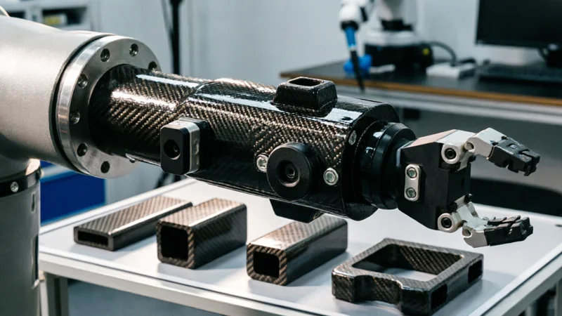
Carbon Fiber Robot End Effector Link — Custom Shape & Sensor Integration
Custom-shaped carbon fiber end effector links for robotic arms. Designed for automation integrators and research labs requiring lightweight, rigid connections between the robot wrist and gripper/tool. Can incorporate sensor mounting bosses, cable routing channels, and quick-change interfaces.

Custom Carbon Fiber Musical Instrument Parts
Carbon fiber components for musical instrument manufacturing offering superior dimensional stability, low weight, and consistent acoustic properties. We produce carbon fiber bows, guitar necks, violin chin rests, drum shells, and wind instrument bodies. Carbon fiber instruments are immune to humidity changes and temperature fluctuations that affect wooden instruments.
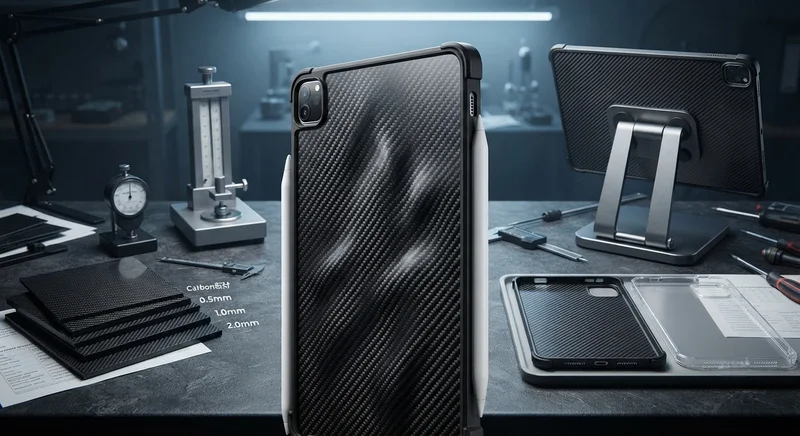
Carbon Fiber Tablet Case — Ultra-Light Protective Shell
Lightweight carbon fiber protective case for tablets and iPads. Molded from T700 3K prepreg with reinforced corner protection. Adds minimal weight while providing superior rigidity and drop protection compared to polycarbonate or silicone cases. Ideal for field workers, enterprise deployments, and professionals requiring durable tablet protection.