
Carbon fiber composite parts are only as good as their cure. A laminate can have perfect fiber alignment, flawless layup, and the right resin chemistry, yet produce a rejected part if the cure cycle ran too hot, too cold, or too short. Traditionally, manufacturers verified the cure by p
Introduction
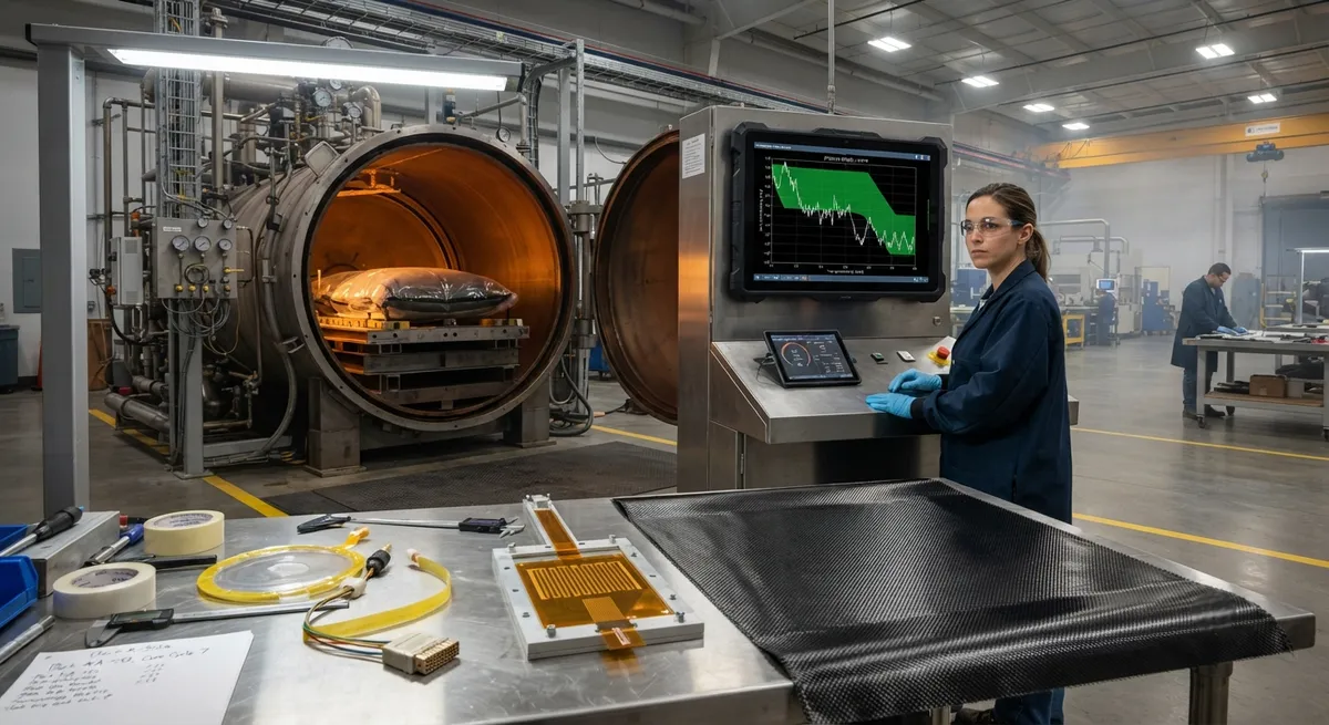
Carbon fiber composite parts are only as good as their cure. A laminate can have perfect fiber alignment, flawless layup, and the right resin chemistry, yet produce a rejected part if the cure cycle ran too hot, too cold, or too short. Traditionally, manufacturers verified the cure by processing witness coupons alongside production parts and testing them days later — a sampling approach that cannot catch a single out-of-spec cycle. Dielectric cure monitoring changes this by placing sensors directly on or inside the production part, measuring the resin's electrical behavior in real time, and converting that signal into a live degree-of-cure value while the part is still in the oven, autoclave, or mold.
For quality managers and process engineers, in-situ monitoring answers the question that sampling cannot: did this specific part cure correctly, right now? This article covers how interdigital dielectric sensors work, where they are placed for reliable data, how the raw signal correlates with degree of cure, and the cost reality of adding monitoring to autoclave and resin transfer molding (RTM) production lines.
How Dielectric Cure Monitoring Works
Dielectric analysis (DEA) measures two electrical properties of a resin as it changes during cure: capacitance and conductance. An interdigital sensor — a flat ceramic or polyimide substrate with two comb-shaped electrode patterns on its surface — is placed in contact with the resin. An alternating electric field is applied, and the sensor returns the material's dielectric constant (permittivity) and ionic conductivity as functions of frequency and time. Early in the cycle, low-viscosity resin allows ions to migrate freely, producing high conductivity. As crosslinking progresses, the resin stiffens, ion mobility drops, and conductivity falls. This ionic conductivity is the workhorse signal for cure monitoring.
- Ionic conductivity: Tracks viscosity and crosslink density; the primary signal for degree-of-cure determination.
- Dielectric constant: Reflects dipole mobility and polar group concentration; useful for detecting cure onset and resin arrival in RTM flow fronts.
- Frequency sweep: Multi-frequency measurements separate ionic conduction from dipole relaxation, improving robustness at the end of cure when the resin is glassy.
Modern systems log data every 1-5 seconds across the full cure cycle and display it alongside the temperature profile, so engineers can compare the actual cure trajectory against the qualified process window in real time.
Sensor Placement for Reliable Data
The value of dielectric monitoring depends almost entirely on where the sensors go. A sensor that reads the mold wall rather than the part measures something that is not the part. Placement rules that work in production are straightforward:
- On the tool surface near the part: The most common arrangement — a thin film sensor is taped or vacuum-bagged against the tool face where it contacts the laminate edge. It reads the resin that flows to the edge, which correlates well with bulk cure when flow is uniform.
- Between plies in the laminate: For thick sections or parts where the interior cures slower than the surface, a disposable interdigital sensor can be laid up between plies and left in the part. This measures the through-thickness cure gradient directly — critical for thick laminates over 10 mm.
- In the mold cavity for RTM: Sensors flush-mounted in the tool wall track resin arrival and gelation point at each gate and vent, turning a blind injection into a monitored event.
- At fastening or bolt-hole locations: Placing sensors where the part will later be drilled ensures the monitoring point is a structural location rather than a benign cosmetic area.
The trade-off is cost versus fidelity. In-part sensors are the most accurate but are consumed with the part; tool-mounted sensors are reusable for hundreds of cycles but read only the edge or surface. Most manufacturers run a mix: embedded sensors on first articles and critical parts, tool-mounted sensors on every production cycle.
Correlating the Signal with Degree of Cure
The raw conductivity curve is useful, but quality systems need a number. The standard approach is to correlate the dielectric signal with degree of cure measured by differential scanning calorimetry (DSC) on resin samples, then map the in-situ curve onto the DSC-derived relationship. In practice, two conversions dominate:
| Method | Signal Used | Output | Typical Accuracy vs DSC | Limitations |
|---|---|---|---|---|
| Ionic conductivity log-log extrapolation | Conductivity vs time | Gelation and vitrification points | Event timing ±2-5 min | Less reliable in glassy end-of-cure |
| Normalized conductivity to degree-of-cure | Conductivity normalized to a calibration cure | Degree of cure 0-100% | ±3-7% in the 0.5-0.95 range | Requires per-resin calibration |
| Multi-frequency dielectric relaxation | Frequency-dependent permittivity | Degree of cure with vitrification tracking | ±2-5% | More complex signal processing |
The correlation holds because ionic conductivity tracks the same physical quantity that DSC measures — the extent of crosslinking. The key engineering step is calibration: cure a reference sample of the exact resin batch and fiber volume fraction, build the conductivity-to-degree-of-cure lookup curve, and validate it against DSC on a small sample set. Once calibrated, the in-situ reading becomes a pass/fail gate that can release a part for downstream processing immediately after the cycle, instead of waiting for witness coupon testing.
Production Benefits and Cost Reality
The business case for dielectric cure monitoring rests on three measurable outcomes: reduced scrap, shorter release times, and better process data. The table below summarizes typical results reported across aerospace and automotive composite production:
| Outcome | Typical Reported Gain | Source of Gain |
|---|---|---|
| Cure-related scrap reduction | 30-60% fewer cure-caused rejects | Early detection of under-cure and temperature excursions |
| Part release time | Hours to minutes (witness coupon testing eliminated) | In-situ degree-of-cure gate |
| Cycle time optimization | 5-15% shorter cure cycles | Cycle stopped at verified full cure, not conservative schedule |
| Equipment utilization | Higher autoclave throughput | Faster turnaround per batch |
On cost, the picture is increasingly favorable. Disposable in-part sensors run roughly $15-60 each depending on temperature rating and quantity; reusable tool-mounted sensors amortize to a few dollars per cycle over several hundred cycles. A monitoring channel (sensor + analyzer channel) typically costs $2,000-5,000, and a multi-channel system covering a full autoclave load runs $20,000-60,000 — a small fraction of the value of a single rejected aerospace part, which can exceed $50,000 in material and labor. For high-rate automotive RTM programs, per-part sensor cost must be carefully budgeted, but the scrap savings typically pay back the investment within the first production year.
Integration with Existing Quality Systems
Dielectric cure monitoring slots into a standard manufacturing execution system (MES) as a new data source. The sensor data is logged per part serial number, creating a permanent cure record that satisfies the traceability requirements of aerospace quality systems such as AS9100 and NADCAP. In practice, manufacturers use the data in three tiers: real-time alerts that flag an excursion while the cycle can still be recovered, an automated part release gate at cycle end, and an aggregate database for continuous improvement — correlating cure signatures with downstream non-conformances to refine process windows. The same sensors can double as in-situ sensors for resin arrival detection in RTM and for post-cure monitoring, extending the equipment's value beyond a single step.
Frequently Asked Questions
How does dielectric cure monitoring compare with thermocouple-based monitoring?
Thermocouples measure temperature only, and temperature is an indirect proxy for cure. A part can reach the correct temperature profile yet still be under-cured if the resin batch is off-spec or the heating rate is wrong. Dielectric sensors measure the resin's actual state — its ionic conductivity and permittivity — which responds directly to crosslink density. The two are complementary: thermocouples confirm the thermal environment, dielectric sensors confirm the chemical state. Most production systems record both, using temperature for process control and dielectric data for the cure release decision.
Can dielectric sensors be used inside the part, and are they left in the final product?
Yes. Interdigital sensors manufactured on thin polyimide film are thin enough (0.1-0.5 mm) to be laid up between plies and vacuum-bagged with the laminate. They are consumed with the part — either left in a non-structural region or, more commonly, placed where a hole will later be drilled or a region that will be trimmed away. In-part sensors give the most accurate reading of through-thickness cure gradients, which matter for laminates thicker than about 10 mm. For standard panels, tool-mounted sensors read the laminate edge and provide adequate correlation with bulk cure.
Is dielectric monitoring worth it for small or low-volume production?
For low-volume production the economics still work when part value is high — a single aerospace or defense part can exceed the full cost of the monitoring system, so preventing one reject pays for the equipment. For low-value, low-volume work, tool-mounted reusable sensors and a single-channel analyzer can monitor critical cycles at a few thousand dollars of upfront cost. The minimum viable setup is one calibrated channel on the most expensive or most failure-prone part in the program.
Conclusion
Dielectric cure monitoring moves carbon fiber composite quality control from sampling to full verification. By placing interdigital sensors on the tool surface or inside the laminate, manufacturers capture a real-time degree-of-cure signal that correlates with DSC measurements to within a few percent, release parts in minutes instead of days, and reduce cure-related scrap by 30-60%. The calibration step is the engineering core of the method, and the per-part cost is small relative to the value of a rejected composite structure.
For manufacturers evaluating in-situ cure monitoring, the practical starting points are sensor placement strategy, resin-specific calibration, and integration with the existing quality system. Explore our carbon fiber reinforcement and prepreg range to pair with your cure monitoring program, or contact our engineering team to discuss material and process qualification for your composite line.
Part of topic
Related Articles
- Carbon Fiber Drone Blades and Propellers: Stiffness, Balance and Noise Reduction
- Fiberglass Filament Wound Tubes: Cost-Effective Alternative to Carbon Fiber
- Filament Wound Epoxy Tube Design: Wall Thickness, Fiber Angle and Load Optimization
- Filament Wound Epoxy Tubes: Testing Standards and Quality Assurance
- Filament Wound Epoxy Tubes Manufacturing: Process and Quality Control
- Filament Wound Fiberglass Tube: Process Parameters and Performance vs Carbon Fiber
Interested in Our Products?
Contact our team for competitive pricing and technical specifications.
Get a QuoteRelated Products

Carbon fiber standard plate-3k stripe
Lightweight, ultra-rigid standard sheets for drone fuselages, robot housings, facades and structural applications.

Carbon Fiber Plate — 3K Twill T700 3.0mm
Medium-thickness 3.0mm carbon fiber plate offering significantly higher load capacity while maintaining attractive 3K twill finish. Suitable for structural brackets, reinforcement plates, and load-bearing panels.

Carbon Fiber Plate — 3K Twill T700 1.5mm
Thin 1.5mm carbon fiber plate with 3K twill weave surface. Lightweight and stiff, commonly used for covers, panels, drone bodies, and applications requiring a premium aesthetic appearance.

Custom Carbon Fiber Medical Device Components
Medical-grade carbon fiber components manufactured for imaging equipment, surgical instruments, and patient support systems. Carbon fiber's radiolucency (X-ray transparency) and high strength-to-weight ratio make it ideal for CT scanner beds, wheelchair frames, surgical robot arms, and MRI-compatible accessories. Biocompatible resin systems available.

Square Carbon Fiber Tube — 3K Twill T700
Square cross-section carbon fiber tube manufactured with 3K twill weave for torsional strength. Preferred for structural frames, trusses, and support columns where rectangular geometry offers design flexibility.