
Compression molding of carbon fiber parts is the dominant process for producing structural brackets at production volumes. Automotive seat brackets, battery tray mounts, suspension spring seats, aerospace interior brackets, and robotic arm mounting plates all follow the same logic: a pr
Introduction
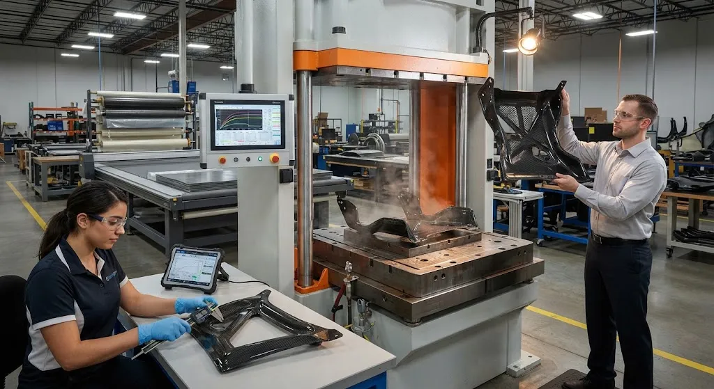
Compression molding of carbon fiber parts is the dominant process for producing structural brackets at production volumes. Automotive seat brackets, battery tray mounts, suspension spring seats, aerospace interior brackets, and robotic arm mounting plates all follow the same logic: a pre-formed carbon fiber charge is placed in a heated steel mold, the press closes, heat and pressure cure the matrix, and a net-shape part emerges in minutes. The process is attractive because it combines short cycle times with the high fiber volume fractions that give carbon fiber its mechanical advantage.
Yet the gap between a prototype bracket and a consistent series part is defined by process windows — the ranges of temperature, pressure, and timing within which the material behaves predictably. Outside those windows, the same mold and the same material produce voids, fiber wash, or dimensional drift that fails quality gates. This article examines the process windows that matter for compression-molded carbon fiber brackets, the defects that appear when they are violated, and the validation routine that locks in consistency across thousands of parts.
Why Process Consistency Matters for Brackets
Brackets occupy a specific niche in composite structures. They are small enough to mold in large batches, structural enough that failure is unacceptable, and — unlike large panels — they are often invisibly hidden inside a vehicle or machine, so quality issues surface only in testing or in the field. A seat bracket in a passenger car, for example, must survive repeated load cycles, vibration, and corrosion over a 15-year service life while meeting a dimensional tolerance of around 0.5 mm at the mounting holes.
Because brackets are load-bearing, the strength scatter of the molded part matters as much as its average strength. If a molded batch shows a coefficient of variation of 12 percent in flexural strength instead of the 5 percent typical of a well-controlled window, designers must downgrade the allowables used in the stress analysis, which erases the weight saving that justified composites in the first place. Process window control is therefore not a quality nicety — it is the economic foundation of the application.
How Compression Molding of Carbon Fiber Parts Works
The process begins with a charge: either a stack of cut prepreg plies, a sheet molding compound (SMC) blank, or a preshaped preform that has been tailored to the bracket geometry. The operator or robot places the charge into the open lower mold half, the press closes at a controlled rate, and the applied pressure forces the material to confirm to the cavity while the heated tool raises the matrix above its cure temperature.
Two material families dominate bracket molding:
- Carbon fiber epoxy prepreg: Oriented unidirectional or fabric plies give the highest fiber volume fraction and the best mechanical properties. Cycle times are longer, and the charge must be laid up and staged before molding.
- Carbon fiber SMC or BMC: Randomly oriented fiber chips in a paste matrix flow easily into complex geometries, giving fast cycles and low material cost, but fiber volume fraction and stiffness are lower than prepreg.
For parts that need alignment of load paths, a hybrid is common: a unidirectional prepreg spine is placed in the high-load region while SMC fills the rest of the geometry. The press then applies full pressure, holds at cure temperature until the matrix reaches the required degree of cure, and the part is ejected, trimmed, and post-cured if the chemistry requires it.
Key Process Parameters: The Molding Window
Consistent brackets come from controlling six interacting parameters. The table below summarizes the windows typical for carbon fiber epoxy prepreg molding of small-to-medium brackets:
| Parameter | Typical Window | Effect on Part Quality |
|---|---|---|
| Mold temperature | 135-160 °C (epoxy) | Too low: undercure and tacky parts; too high: matrix degradation and sticking |
| Molding pressure | 1.5-6 MPa | Too low: voids and dry spots; too high: fiber wash and flash |
| Press close speed | 2-15 mm/s | Fast close forces fiber movement; slow close risks premature gelation |
| Cure dwell time | 5-15 min | Sets degree of cure and glass transition temperature |
| Charge coverage | 70-95% of cavity area | Low coverage: knit lines and voids; full coverage: trapped air and overflow |
| Tool vacuum | 25-100 kPa partial vacuum | Removes volatiles and entrapped air during flow |
Two parameters deserve special attention for brackets. The first is charge coverage: a charge that covers too little of the cavity forces the material to flow long distances, which drags fiber orientation away from the design intent and creates knit lines where flow fronts meet. The second is cure dwell time, which determines whether the matrix reaches full glass transition temperature — short dwells create parts that pass mechanical tests fresh from the mold but soften in elevated-temperature service.
Common Defects and Their Root Causes
When a process window is violated, the failure modes are consistent and diagnosable:
- Voids and porosity: Usually caused by insufficient pressure, trapped volatiles, or charges with high moisture content. Porosity above roughly 2 percent reduces shear strength in loaded brackets.
- Fiber wash: The displacement of fiber bundles by flowing resin, typically from fast press closing or excessive pressure. It appears as regions with resin-rich surfaces and low fiber density.
- Short shots and knit lines: The result of low charge coverage, cold molds, or elongated flow paths. They create unfilled areas or weak seams where flows meet.
- Warpage: Caused by asymmetric cooling, unbalanced laminate layup, or post-ejection relaxation. Brackets with thin and thick sections are prone to residual stress distortion.
- Thickness variation: A symptom of pressure loss, oversized charge banks, or thermal expansion mismatch between tool and part.
A robust diagnostic approach is to cut a sample bracket from each trial run, photograph the cross-section, and compare void content against the acceptance limit. This direct evidence ties each defect signature to the parameter that caused it, so the window can be re-centered rather than guessed at.
Process Validation for Series Production
Reaching a consistent bracket production state requires a structured validation loop. The routine typically proceeds in four stages. First, a design of experiments maps the molding window: temperature, pressure, close speed, and dwell are varied around the nominal recipe, and the resulting parts are measured for void content, thickness, warpage, and mechanical properties. Second, the process is locked to the center of the window — not the edge — so that normal drift in material batch or ambient temperature stays inside the acceptable range. Third, statistical process control is introduced: key parameters such as mold temperature at each zone and actual close force are logged for every cycle, and control charts flag drift before parts fall out of specification.
For higher-criticality brackets, the fourth stage is capability analysis. Molded test coupons are taken at scheduled intervals, tested for interlaminar shear strength and flexural modulus, and the resulting capability indexes (Cp and Cpk) are tracked. A Cpk above 1.33 for the critical properties is the common acceptance gate for automotive and aerospace-qualified suppliers. When capability degrades, the logged process data makes it possible to trace the drift to a specific parameter and recenter the window with a small, targeted adjustment.
Choosing the Right Molding Route
Compression molding is one of several press-based processes for bracket production, and the selection depends on volume, mechanical requirements, and geometry. The table below compares the main routes:
| Criterion | Prepreg Compression | SMC Compression | High-Pressure RTM |
|---|---|---|---|
| Cycle time per part | 5-15 min | 2-5 min | 3-10 min |
| Fiber volume fraction | 55-65% | 25-45% | 50-60% |
| Tensile modulus potential | High (oriented) | Moderate (random) | High (oriented) |
| Tooling cost | High | Medium | High |
| Best fit | Structural brackets, low-to-medium volume | Styling-and-load parts, high volume | Complex ribbed brackets, medium volume |
For load-bearing brackets where weight saving is the point of using carbon fiber, prepreg compression molding remains the reference process because it preserves fiber orientation and achieves the highest fiber volume fraction. SMC wins when cycle time and cost dominate and the loads are moderate. High-pressure RTM competes when the bracket has deep ribs or inserts that a solid charge cannot fill cleanly.
Frequently Asked Questions
What is the difference between compression molding and transfer molding of carbon fiber parts?
In compression molding, a preplaced charge is squeezed into shape by the closing press, and the material flows only as far as the cavity requires. In transfer molding, the charge is first loaded into a separate chamber, then pushed through runners and gates into the closed cavity under pressure. Transfer molding handles complex geometries with fine details more consistently, but the runner system creates scrap and the gate areas can become resin-rich. For simple bracket geometries, compression molding is simpler, cheaper, and wastes less material.
How long does a typical compression molding cycle take for a carbon fiber bracket?
For a small automotive bracket, the full cycle is typically 5-15 minutes with epoxy prepreg: around 3-5 minutes for loading and press closure, 3-8 minutes of cure dwell at temperature, and 1-2 minutes for ejection and cleaning. SMC-based brackets can run in 2-5 minutes because the paste matrix cures faster. Total cycle time is driven mainly by the cure dwell, which is set by the matrix chemistry and the part's minimum cure requirement.
How do I reduce void content in compression-molded carbon fiber brackets?
Start by confirming the charge is dry — moisture in the resin is a common void source. Then verify molding pressure is within the window (typically 1.5-6 MPa for prepreg) and that tool vacuum or breathing cycles are removing volatiles during the flow phase. Increase charge coverage so material does not have to flow long distances, and slow the press close speed to avoid trapping air pockets. Cross-section microscopy on a sample part will show whether remaining voids are concentrated near knit lines, which points to a flow problem rather than a pressure problem.
Conclusion
Compression molding of carbon fiber parts delivers the cycle times and mechanical performance needed for production brackets, but only when the process window is defined, documented, and held. The combination of charge design, molding parameters, and statistical process control separates a supplier that molds occasional good brackets from one that molds consistently good brackets. Buyers evaluating a bracket supplier should ask for process window documentation, CpK data on critical properties, and cross-section void evidence — not just a sample part.
YongXian supplies carbon fiber fabrics, unidirectional prepreg, and reinforcement materials for compression-molded structural components. Explore our carbon fiber product range or contact our engineering team to discuss material systems and process support for your bracket program.
Part of topic
Related Articles
- Bio-Based Carbon Fiber Precursors: Lignin and Polyethylene for Low-Cost Production
- Large-Tow Carbon Fiber Cost Analysis: 48K vs 60K Price-Performance Comparison
- Carbon Fiber-Resin Interface Bonding: Surface Treatment and Coupling Agent Optimization
- Digital Twin for Carbon Fiber Manufacturing: Real-Time Process Monitoring and Defect Prevention
- Thermoplastic Carbon Fiber Welding for Automotive: Ultrasonic and Induction Welding Process Windows
- Large-Tow Carbon Fiber Wet Spinning: Process Optimization for 48K/60K Production Efficiency
Interested in Our Products?
Contact our team for competitive pricing and technical specifications.
Get a QuoteRelated Products

Carbon Fiber Fishing Rod Blank
High-quality carbon fiber fishing rod blank manufactured from multiple grades of Toray carbon fiber cloth. Available in a wide range of lengths, powers, and actions for freshwater and saltwater applications. Suitable for OEM rod building.

Carbon Fiber Plate — 3K Twill T700 3.0mm
Medium-thickness 3.0mm carbon fiber plate offering significantly higher load capacity while maintaining attractive 3K twill finish. Suitable for structural brackets, reinforcement plates, and load-bearing panels.

Carbon Fiber Plate — 3K Twill T700 1.5mm
Thin 1.5mm carbon fiber plate with 3K twill weave surface. Lightweight and stiff, commonly used for covers, panels, drone bodies, and applications requiring a premium aesthetic appearance.

Square Carbon Fiber Tube — 3K Twill T700
Square cross-section carbon fiber tube manufactured with 3K twill weave for torsional strength. Preferred for structural frames, trusses, and support columns where rectangular geometry offers design flexibility.
Carbon Fiber Drone Arm
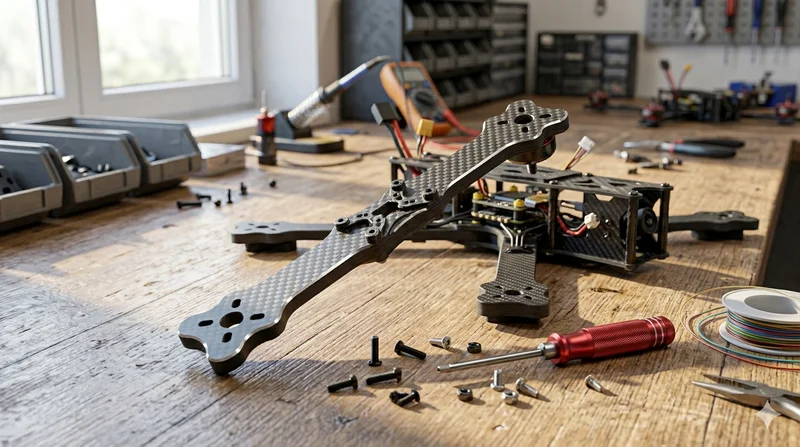
Precision-molded carbon fiber drone arm combining unidirectional fiber for stiffness and woven layers for torsional strength. Designed for FPV, photography, and industrial drone platforms. Each arm is CNC-machined to exact specifications.