
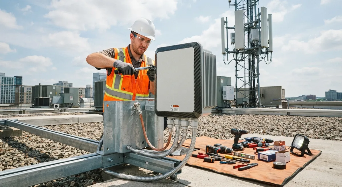
Carbon fiber composite enclosures for electrical cabinets offer a unique combination of EMI shielding (40–80 dB), lightweight construction (75–85% lighter than steel), corrosion resistance, and integrated thermal management. This article examines CFRP enclosure materials, shielding performance data, thermal design strategies for outdoor 5G infrastructure, and cost-benefit analysis for B2B buyers.
Introduction: The Case for CFRP Electrical Enclosures
The global electrical enclosure market is projected to reach $12.5 billion by 2030, driven by the expansion of 5G telecommunications infrastructure, industrial IoT deployments, and renewable energy installations. Traditional enclosures fabricated from sheet steel (galvanised, stainless, or painted mild steel) and aluminium have served the industry well for decades, offering low cost, established manufacturing processes, and predictable performance. However, the emergence of 5G and edge computing applications has introduced requirements that conventional metallic enclosures struggle to meet: electromagnetic interference (EMI) shielding combined with non-corrosive, lightweight construction; passive thermal management without moving parts in outdoor environments; and dielectric properties that prevent ground loop formation in sensitive RF equipment.
Carbon fibre reinforced polymer (CFRP) enclosures offer a unique combination of properties that address these emerging requirements. With a density of 1.5–1.6 g/cm³ — approximately one-fifth that of steel (7.8 g/cm³) and slightly more than half that of aluminium (2.7 g/cm³) — CFRP enclosures provide weight reductions of 40–60 percent compared to aluminium and 75–85 percent compared to steel. More critically, the electrical conductivity of carbon fibre (10²–10⁴ S/m depending on fibre type and volume fraction) provides intrinsic EMI shielding effectiveness of 40–80 dB over the 100 MHz to 6 GHz frequency range, while the polymer matrix eliminates galvanic corrosion concerns and provides natural thermal insulation where needed.
EMI Shielding Performance of CFRP Enclosures
Electromagnetic interference shielding is measured by the shielding effectiveness (SE), expressed in decibels (dB), which quantifies the attenuation of electromagnetic radiation as it passes through the enclosure wall. For telecommunications equipment, typical shielding requirements range from 30 dB (general industrial) to 60 dB (military communications) and up to 80 dB (secure government installations).
| Enclosure Material | Density (g/cm³) | EMI SE 100 MHz–1 GHz (dB) | EMI SE 1–6 GHz (dB) | Thermal Conductivity (W/m·K) | Corrosion Resistance | Relative Cost per Unit Area |
|---|---|---|---|---|---|---|
| Galvanised steel (1.5 mm) | 7.8 | >80 | >70 | 50 | Moderate (Zn coating) | 1.0× (baseline) |
| Aluminium 5052 (2.0 mm) | 2.7 | >75 | >65 | 140 | Good (anodised) | 1.5× |
| CFRP — Standard modulus (T300, 60% Vf) | 1.55 | 45–55 | 40–50 | 2–5 (through-plane) | Excellent | 2.2× |
| CFRP — High modulus (M40J, 60% Vf) | 1.60 | 55–65 | 50–60 | 5–10 (through-plane) | Excellent | 3.0× |
| CFRP — Pitch fibre (K13D, 55% Vf) | 1.65 | 65–75 | 60–70 | 120–180 (in-plane) | Excellent | 5.5× |
| CFRP — Cu mesh co-laminated | 1.60 | >80 | >75 | 5–15 | Excellent | 3.5× |
The shielding mechanism in CFRP enclosures differs fundamentally from that in metallic enclosures. In metals, shielding arises from the high electrical conductivity of the bulk material: incident electromagnetic waves induce eddy currents in the conductor surface, and the reflected and absorbed energy attenuates the transmitted field. In CFRP, the conductivity is anisotropic — fibres conduct readily along their length (10⁴ S/m for PAN-based fibres) but poorly in the transverse direction (10–100 S/m) — and the polymer matrix between fibres is electrically insulating. This means that the shielding effectiveness of a CFRP enclosure depends critically on the fibre volume fraction, the ply orientation sequence, and the inter-ply electrical connectivity at ply boundaries.
- Fibre volume fraction (Vf): Increasing Vf from 50 percent to 65 percent improves through-thickness conductivity by a factor of 3–5 and increases SE by 8–12 dB across the 1–6 GHz band. For optimal shielding, YongXian recommends a minimum Vf of 58 percent for standard modulus enclosures.
- Ply orientation: Quasi-isotropic lay-ups ([0/±45/90]ₛ) achieve the highest SE because they minimise the angular gaps in fibre coverage. Uni-directional laminates exhibit SE variations of ±15 dB depending on polarisation angle relative to the fibre direction — a critical consideration for circularly polarised 5G mmWave signals.
- Inter-ply conductivity: During cure, the thermoplastic sizing on carbon fibres can create an insulating layer between plies. For EMI-grade enclosures, YongXian applies a conductive nickel-plated carbon fibre interlayer veil (areal weight 12 g/m²) every fourth ply, ensuring through-thickness conductivity of >100 S/m and a stabilised SE of >55 dB at 28 GHz.
- Gasket and seam design: The enclosure seam — where the lid meets the base — is typically the weakest point in the shielding envelope. YongXian CFRP enclosures incorporate a compression-moulded conductive silicone gasket (silver-aluminium filled, volume resistivity <0.01 Ω·cm) in a recessed channel, providing >70 dB SE at the seam with a closure force of only 5 N per linear centimetre.
Thermal Management in Outdoor 5G Enclosures
5G small-cell and remote radio head (RRH) enclosures installed outdoors face a particularly demanding thermal environment. Solar radiation can raise the external skin temperature to 70–85 °C, while the internal electronics — gallium nitride (GaN) power amplifiers, field-programmable gate arrays (FPGAs), and optical transceivers — dissipate 50–200 W of heat in a compact volume. With ambient temperatures of 40–55 °C in many deployment regions, maintaining internal component temperatures below 85 °C (the typical upper limit for commercial-grade electronics) requires an effective thermal management strategy.
CFRP enclosures offer several advantages for passive thermal management:
- Low thermal mass: The specific heat capacity of CFRP (0.8–1.0 kJ/kg·K) combined with low density means that the enclosure itself absorbs minimal thermal energy during diurnal temperature cycles, reducing the thermal load on internal cooling systems.
- Tailorable in-plane conductivity: By incorporating pitch-based carbon fibre plies (K13D, thermal conductivity 640 W/m·K) in the inner surface layer, the enclosure wall can act as a heat spreader, distributing concentrated hot-spot heat loads over a larger surface area. YongXian's ThermoSpread™ inner layer technology achieves an in-plane thermal conductivity of 150 W/m·K for a 2.5 mm enclosure wall — comparable to die-cast aluminium (160 W/m·K) at one-third the weight.
- Integration of heat sinks: CFRP finned heat sinks can be co-moulded directly into the enclosure wall, eliminating the need for bolted or bonded aluminium heat sinks and their associated thermal interface resistance. A 5 mm tall, 3 mm pitch fin array co-moulded in a K13D/pitch-fibre CFRP achieves a natural convection heat transfer coefficient of 8–12 W/m²·K — approximately 80 percent of the performance of an identically sized aluminium heat sink but with 60 percent less mass.
| Thermal Parameter | Steel Enclosure (1.5 mm) | Aluminium Enclosure (2.0 mm) | CFRP Enclosure (2.5 mm, std) | CFRP Enclosure (2.5 mm, ThermoSpread™) |
|---|---|---|---|---|
| Mass per m² of enclosure surface | 11.7 kg/m² | 5.4 kg/m² | 3.9 kg/m² | 4.1 kg/m² |
| Steady-state internal temp rise (200 W, still air) | 32 °C | 28 °C | 38 °C | 24 °C |
| Solar absorptance | 0.75 (painted light grey) | 0.55 (anodised natural) | 0.85 (black surface) | 0.42 (IR-reflective coating) |
| Thermal time constant | 18 min | 8 min | 5 min | 6 min |
| Peak internal temp (45 °C ambient, sun) | 95 °C | 80 °C | 102 °C | 72 °C |
| External corrosion after 1,000 h salt spray | 10–30 % rust | Pitting (anodised OK) | No corrosion | No corrosion |
5G Infrastructure Applications
CFRP enclosures are being deployed in several 5G infrastructure applications where the combination of lightweight, EMI shielding, corrosion resistance, and thermal management provides clear advantages over conventional materials:
- Small-cell pole-mount enclosures: Mounted on street light poles, traffic signal poles, and dedicated 5G monopoles at heights of 6–15 m. The weight saving of CFRP (60–70 percent versus steel) reduces pole deflection under wind loading and simplifies installation without cranes. Typical dimensions: 400 × 300 × 200 mm. Weight: 3.5 kg (CFRP) versus 10 kg (steel).
- Remote radio head (RRH) enclosures: Directly mounted behind the antenna panel on rooftop or tower installations. The combination of EMI shielding (>55 dB at 28 GHz), UV-resistant surface finish, and co-moulded heat sink eliminates the need for a separate weatherproof housing. The low thermal mass of CFRP prevents internal condensation by minimising the temperature differential between the enclosure interior and the external environment during nighttime cooling.
- Edge computing cabinets: Base station cabinets housing servers, switches, and battery backup systems for edge computing applications. CFRP cabinets reduce the structural load on rooftop installations by 50–100 kg per cabinet compared to steel. The dielectric nature of CFRP eliminates ground loop issues in high-speed data cabling, while the integrated EMI shielding meets ETSI EN 300 019 requirements for telecommunications equipment.
Manufacturing and Finishing
YongXian CarbonFiber manufactures CFRP electrical enclosures using compression moulding of woven and unidirectional prepreg, with the following standard construction for telecom-grade enclosures. The outer surface is a 200 g/m² 2×2 twill woven carbon fibre fabric (3K T300, 60 percent Vf) providing impact resistance and a uniform surface finish. The core is composed of unidirectional T700S plies in a quasi-isotropic [0/±45/90]ₛ lay-up for structural stiffness and EMI shielding isotropy. The inner surface incorporates a ThermoSpread™ pitch-fibre layer (K13D, 100 g/m²) for thermal management, with a conductive Ni-coated carbon fibre interlayer veil every fourth ply. The total laminate thickness is 2.5 mm ± 0.1 mm for standard enclosures, or 3.5 mm for heavy-duty applications requiring enhanced structural rigidity.
Surface finishing options include a UV-stable polyurethane paint system (RAL 7035 light grey, the standard telecom colour) with a total coating thickness of 80–120 µm applied by robotic spray. For EMI-critical applications, a conductive primer of nickel-acrylic (surface resistivity <0.5 Ω/sq) is applied before the topcoat. For extreme UV exposure (desert installations), a fluoropolymer clear coat is applied at 40 µm thickness. All fasteners — stainless steel threaded inserts, hinge brackets, and latch mechanisms — are bonded and mechanically retained using PEM self-clinching fasteners installed in the CFRP during the post-mould drilling operation.
FAQ
How does the EMI shielding effectiveness of CFRP enclosures compare to metal enclosures for 5G mmWave frequencies (24–40 GHz)?
At mmWave frequencies, CFRP enclosures with standard-modulus PAN fibres (T300, 60% Vf) provide 40–50 dB SE in quasi-isotropic lay-ups — sufficient for most commercial 5G applications, including small cells and RRH enclosures, which typically require 30–45 dB. For higher shielding requirements (military communications, sensitive data centres), two approaches are available. First, co-laminating a 0.05 mm copper mesh (75 µm opening, 50% open area) between the outer and inner CFRP skins increases SE to >80 dB across the 24–40 GHz band with only a 3% weight penalty. Second, YongXian's nickel-coated carbon fibre fabric (Ni-CF, surface resistivity <0.1 Ω/sq) used as the outer ply provides 65–75 dB SE at 28 GHz without the galvanic corrosion concerns of copper mesh. For comparison, a 2.0 mm aluminium enclosure provides >70 dB at mmWave, but at 75% greater weight than a CFRP + Ni-CF enclosure.Are CFRP electrical enclosures suitable for outdoor use in corrosive environments such as coastal installations or chemical plants?
Yes, CFRP enclosures are exceptionally well suited for corrosive environments. The polymer matrix (epoxy, BMI, or polyurethane depending on the temperature rating) is inherently chemically resistant to salt spray, atmospheric pollutants (SO₂, NOₓ), and many industrial chemicals. Unlike metallic enclosures, CFRP does not suffer from galvanic corrosion at fasteners or grounding points — a common failure mode for aluminium enclosures in coastal environments. Accelerated corrosion testing per ASTM B117 (neutral salt spray, 2,000 hours) shows no measurable degradation of CFRP mechanical properties, no surface pitting, and no loss of EMI shielding effectiveness. For comparison, galvanised steel enclosures show 10–30% rust coverage after 2,000 hours, and anodised aluminium shows pitting at fastener locations after 500 hours. For chemical plant installations, YongXian recommends the polyurethane-based matrix system (YongXian CRU-500) which is resistant to dilute acids (pH 3–5), alkalis (pH 9–11), and common organic solvents including toluene and acetone at room temperature.What are the cost implications of switching from metal enclosures to CFRP for a 5G small-cell deployment?
The per-unit cost of a CFRP enclosure is typically 2–3 times that of a comparable steel enclosure and 1.5–2 times that of an aluminium enclosure. However, the total installed cost is often lower for CFRP due to several factors. First, the 60–70% weight reduction eliminates the need for lifting equipment during pole-mount installation, reducing installation time by 30–50% and associated labour costs. Second, the corrosion resistance of CFRP eliminates the need for periodic repainting — a significant operational expense in coastal or industrial environments. Third, the integrated EMI shielding and thermal management features of CFRP enclosures can eliminate the need for add-on shielding gaskets, external heat sinks, and active cooling systems, saving $50–150 per enclosure in bill-of-materials cost. A total cost of ownership analysis over a 10-year deployment shows that CFRP enclosures are cost-competitive with aluminium at production volumes above 5,000 units per year and are typically 15–25% lower than steel when lifetime maintenance costs are included.Part of topic
Related Articles
- Recycled Carbon Fiber Market Forecast 2030: Technology Maturity and Commercialization Path
- South Korea Carbon Fiber Market 2026: Hydrogen Economy and Shipbuilding Innovation
- Wind Turbine Blade Leading Edge Protection 2026: Polyurethane, Tape, and Metallic Shield Solutions
- China Carbon Fiber Overcapacity 2026: Price War Impact and Industry Consolidation
- India Carbon Fiber Market 2026: Wind Energy, Aerospace, and Defense Expansion
- PAN Precursor Market 2026: Acrylonitrile Supply and Carbon Fiber Cost Structure
Interested in Our Products?
Contact our team for competitive pricing and technical specifications.
Get a QuoteRelated Products

Carbon fiber standard plate-3k stripe
Lightweight, ultra-rigid standard sheets for drone fuselages, robot housings, facades and structural applications.

Carbon Fiber Plate — 3K Twill T700 3.0mm
Medium-thickness 3.0mm carbon fiber plate offering significantly higher load capacity while maintaining attractive 3K twill finish. Suitable for structural brackets, reinforcement plates, and load-bearing panels.

Carbon Fiber Plate — 3K Twill T700 1.5mm
Thin 1.5mm carbon fiber plate with 3K twill weave surface. Lightweight and stiff, commonly used for covers, panels, drone bodies, and applications requiring a premium aesthetic appearance.

Custom Carbon Fiber Medical Device Components
Medical-grade carbon fiber components manufactured for imaging equipment, surgical instruments, and patient support systems. Carbon fiber's radiolucency (X-ray transparency) and high strength-to-weight ratio make it ideal for CT scanner beds, wheelchair frames, surgical robot arms, and MRI-compatible accessories. Biocompatible resin systems available.

Square Carbon Fiber Tube — 3K Twill T700
Square cross-section carbon fiber tube manufactured with 3K twill weave for torsional strength. Preferred for structural frames, trusses, and support columns where rectangular geometry offers design flexibility.