
Most carbon fiber parts are still made by cutting flat fabric and unidirectional (UD) tape into 2D plies and stacking them into a 3D shape. That approach works well for panels and skins, but it struggles the moment a part curves, branches, or needs a hole that does not weaken the struct
Introduction
Most carbon fiber parts are still made by cutting flat fabric and unidirectional (UD) tape into 2D plies and stacking them into a 3D shape. That approach works well for panels and skins, but it struggles the moment a part curves, branches, or needs a hole that does not weaken the structure. Cut edges waste material, dropped plies create stress concentrations, and fiber continuity around a radius is impossible to achieve with a flat sheet. Braided preforms solve these problems at the fiber-architecture level: the reinforcement is deposited directly onto the shape it will reinforce.
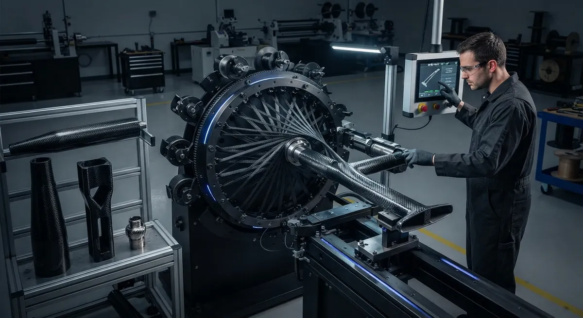
Braiding machines interlace carbon fiber tows around a mandrel or core, producing a tubular, near-net-shape preform whose braid angle, tow count, and coverage can be tuned for the load case. The same process can overbraid a preform over a complex mandrel — a frame, a rib, a fitting — integrating reinforcement exactly where the part needs it. This article examines how braided preforms are made, where overbraiding and tubular structures deliver net-shape efficiency, and how the resulting fiber architecture compares with conventional layups.
How Braided Preforms Are Made
A braiding machine carries spools of carbon fiber tow on carriers that move in a circular pattern, alternating over and under to produce an interlaced tubular braid. Two key parameters define the preform. The braiding angle — the angle between the fibers and the mandrel axis — is set by the ratio of carrier rotation speed to take-up speed, and it controls the balance of axial and hoop strength in the final part. The coverage factor — how completely the braided layer covers the mandrel — depends on tow width, tow count, and braid angle, and it determines how many layers are needed for full coverage.
Two production modes matter in practice. In tubular braiding, the mandrel is a straight or tapered rod, tube, or beam, and the braid is deposited along its length. In overbraiding, the mandrel is a complex shape — a T-junction, a ribbed panel, a fitting — and the braid conforms to its changing cross-section. Overbraiding can deposit reinforcement continuously across features that would otherwise require dozens of hand-cut plies, and it does so with the fibers already in the correct orientation.
Overbraiding: Reinforcement Exactly Where It Is Needed
Overbraiding is the strongest argument for braided preforms in structural parts. A single overbraided layer conforms to a radius, a stiffener, or a boss without cutting, darting, or wrinkling. Where a conventional layup requires small, hand-placed patches around a hole or a frame intersection, an overbraided preform carries continuous fiber across the entire feature, which means no cut-edge stress concentrations and no dropped-ply weak spots.
The practical effect is a dramatic reduction in scrap and labor. Net-shape preforms eliminate the off-cut waste of fabric nesting, which in complex parts can reach 30-40% of purchased material. They also eliminate the labor of ply cutting, ply counting, and patch placement. For a rib or a frame, a single overbraided preform can replace a stack of twenty or more individually cut plies, and the preform can be produced in minutes on an automated braider that runs unattended.
Tubular Structures: Continuous Fibers Around Holes and Junctions
Tubular braided preforms shine wherever a part is essentially a hollow beam or a network of beams: drive shafts, struts, bicycle and automotive frames, antenna masts, and fuselage frames. The braid wraps fiber continuously around the circumference, so hoop strength comes from continuous tow paths rather than from the butt joints of a wrapped fabric. Around cutouts and branch points, braided tows flow around the feature and rejoin, preserving load paths that a cut fabric would interrupt.
Braided tubes also handle taper and section change naturally. The braid angle can be changed along the length by varying take-up speed, letting a single preform have a steeper angle at a highly loaded end and a shallower angle at a lightly loaded one. This continuous, gradual transition is impossible with constant-angle filament winding and very expensive to approximate with fabric layup.
Braid Angle, Coverage, and Mechanical Behavior
The braiding angle is the master control for the laminate's properties. At braid angles near ±30° the fibers lie mostly along the axis, giving high axial stiffness; at angles near ±60° they wrap mostly around the circumference, giving high hoop strength and torsion resistance. Because a single tubular braid produces a balanced ±θ laminate, the part is symmetric by construction, which reduces warpage and distortion compared with unbalanced manual layups.
The trade-off versus conventional materials is a loss of pure unidirectional stiffness: braided fibers are always off-axis by the braid angle, so a braided part is not the right choice where the load is purely axial. In practice, braided preforms are often combined with axial tows inserted along the braid, creating a triaxial braid that restores axial stiffness while keeping the damage tolerance of the interlaced structure. The table below compares typical fiber architectures.
| Fiber Architecture | Fiber Continuity Around Features | Axial Stiffness | Trim Waste | Layup Labor |
|---|---|---|---|---|
| Woven fabric layup | Interrupted at cut edges | Moderate | 20-40% off-cuts | High (cut, stack, patch) |
| Unidirectional tape layup | Interrupted at plies | Highest | Moderate | High (AFP or hand) |
| Biaxial braided preform | Continuous around features | Moderate | Near zero (net-shape) | Low (braider run) |
| Triaxial braided preform | Continuous, plus axial tows | High | Near zero (net-shape) | Low (braider run) |
Because braided tows interlace rather than merely cross, braided laminates also resist delamination better than non-crimp or UD laminates: the through-thickness entanglement acts as a mechanical lock between layers.
Where Braided Preforms Deliver Net-Shape Efficiency
The economic case for braided preforms is strongest in three situations. First, complex geometries with holes, cutouts, and junctions, where fabric off-cuts and patch labor dominate cost. Second, long tubular parts where hoop strength and torsion resistance matter, and where constant-angle winding would waste the design freedom. Third, mid-volume production runs, where the automation of a braiding machine pays off more than the setup cost of a complex tool.
- Structural frames and ribs: Overbraided preforms replace stacks of hand-cut plies around frame intersections.
- Drive shafts and struts: Continuous hoop fibers give torsion and buckling resistance that wrapped fabric cannot match.
- Hollow beams with tapers: Variable braid angle along the length tunes stiffness where it is needed.
- Parts with lightning and impact requirements: Interlaced tows improve damage tolerance and are easier to co-braid with metal or polymer fibers for conductivity.
For lower-volume parts the setup cost of braiding tooling and the minimum quantity of fiber spools can be a barrier, which is why braided preforms are most competitive at medium volumes and for complex shapes.
Frequently Asked Questions
What is the difference between braiding and filament winding?
Filament winding lays one or two tows in helical patterns under tension, typically without interlacing, and changes angle by repositioning the payout head. Braiding interlaces multiple tows from many carriers simultaneously, which locks the fibers together and allows rapid angle changes and overbraiding of complex, non-axisymmetric mandrels. Braiding can follow a changing cross-section; winding is best on simple, mostly convex surfaces.
Can braided preforms be made from prepreg tow?
Yes, but dry braiding is far more common. Dry tows are braided into a preform and then infused with resin in a later step — typically resin transfer molding, vacuum infusion, or resin film infusion. Braiding prepreg tow is possible for small parts but is costly and rarely worth it, since the resin also makes the preform stiff and harder to braid.
How is the braiding angle controlled during production?
The braid angle is set by the ratio between the rotation speed of the carriers and the linear take-up speed of the mandrel. Increasing take-up speed pulls the braid out longer and shallower (lower angle); slowing it packs the braid steeper (higher angle). Modern braiders vary take-up speed along the length, so a single preform can have zones of different braid angle.
Do braided laminates have lower fiber volume fraction than UD laminates?
Generally yes. The interlacing and the crimp where tows cross limit how tightly fibers can pack, so braided laminates typically reach fiber volume fractions around 50-60%, while UD laminates can reach 60-65% or higher. This is a real trade-off, and it is one reason braided preforms are often hybridized with axial tows or unidirectional plies where maximum stiffness is required.
Conclusion
Braided preforms move reinforcement from the cutting table to the fiber architecture itself. Overbraiding deposits continuous carbon fiber exactly where a complex geometry needs it, eliminating trim waste, patch labor, and the stress concentrations of cut edges. Tubular braids deliver hoop continuity and variable braid angles that fabric layup and constant-angle winding cannot. The trade-offs — a moderate loss of axial stiffness and fiber volume fraction — are manageable with triaxial braids and hybridization, while the savings in material, labor, and tooling time are immediate.
Whether you are prototyping a braided drive shaft or quoting an overbraided frame program, the quality of the raw tow determines the quality of the braid. Explore our carbon fiber fabrics and prepreg materials with consistent tensile properties and sizing chemistry, or contact our engineering team to select tow specifications for your braiding program.
Part of topic
Related Articles
- Carbon Fiber Drone Blades and Propellers: Stiffness, Balance and Noise Reduction
- Fiberglass Filament Wound Tubes: Cost-Effective Alternative to Carbon Fiber
- Filament Wound Epoxy Tube Design: Wall Thickness, Fiber Angle and Load Optimization
- Filament Wound Epoxy Tubes: Testing Standards and Quality Assurance
- Filament Wound Epoxy Tubes Manufacturing: Process and Quality Control
- Filament Wound Fiberglass Tube: Process Parameters and Performance vs Carbon Fiber
Interested in Our Products?
Contact our team for competitive pricing and technical specifications.
Get a QuoteRelated Products

Carbon fiber standard plate-3k stripe
Lightweight, ultra-rigid standard sheets for drone fuselages, robot housings, facades and structural applications.

Carbon Fiber Plate — 3K Twill T700 3.0mm
Medium-thickness 3.0mm carbon fiber plate offering significantly higher load capacity while maintaining attractive 3K twill finish. Suitable for structural brackets, reinforcement plates, and load-bearing panels.

Carbon Fiber Plate — 3K Twill T700 1.5mm
Thin 1.5mm carbon fiber plate with 3K twill weave surface. Lightweight and stiff, commonly used for covers, panels, drone bodies, and applications requiring a premium aesthetic appearance.

Custom Carbon Fiber Medical Device Components
Medical-grade carbon fiber components manufactured for imaging equipment, surgical instruments, and patient support systems. Carbon fiber's radiolucency (X-ray transparency) and high strength-to-weight ratio make it ideal for CT scanner beds, wheelchair frames, surgical robot arms, and MRI-compatible accessories. Biocompatible resin systems available.

Square Carbon Fiber Tube — 3K Twill T700
Square cross-section carbon fiber tube manufactured with 3K twill weave for torsional strength. Preferred for structural frames, trusses, and support columns where rectangular geometry offers design flexibility.