
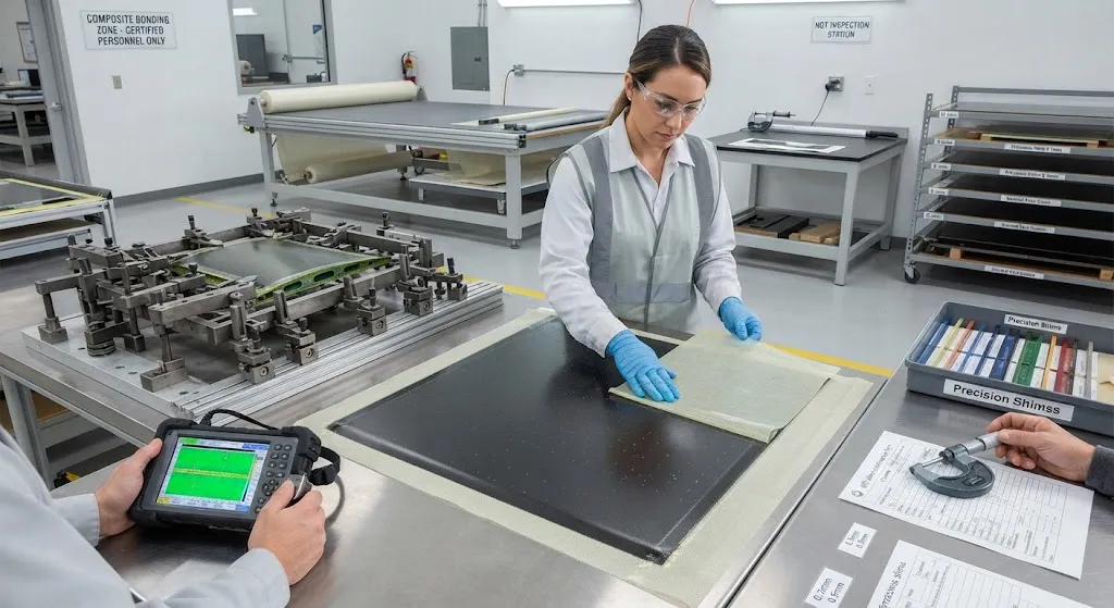
Adhesive bonding is the only joining method that does not damage the fibers it connects: no holes, no fasteners, no stress concentrations left in the laminate by machining. But the adhesive joint has its own hidden variable — the bondline, the thin layer of adhesive between the two adhe
Introduction
Adhesive bonding is the only joining method that does not damage the fibers it connects: no holes, no fasteners, no stress concentrations left in the laminate by machining. But the adhesive joint has its own hidden variable — the bondline, the thin layer of adhesive between the two adherends, typically 0.1-0.3 mm thick. That sub-millimeter dimension carries an outsized share of the joint's reliability. Make it too thin and the bondline starves, peel stresses concentrate at the joint edges, and the interface risks weak-adhesion failure modes that look perfect on a machine drawing. Make it too thick and the shear strength drops, voids appear, and the excess adhesive becomes a source of crack initiation. In aerospace and structural composite practice, bondline thickness is controlled as carefully as any dimension on the part, with tolerances of plus or minus 0.05 mm not unusual on critical joints.
This article explains why bondline thickness governs joint mechanics, compares the three main control methods — shims, carrier films and paste additives — with a data table, and reviews how nondestructive inspection and acceptance testing verify the result in production.
Why Bondline Thickness Governs Joint Mechanics
A bonded joint transfers load through shear over the overlap area, but the stress distribution is never uniform: peel stresses concentrate at the ends of the overlap, and their magnitude depends strongly on the adhesive thickness between the adherends. A thinner bondline produces a stiffer, more concentrated load transfer at the overlap ends, which raises peak peel stress. A thicker bondline lowers the peak but spreads load transfer over a longer effective length, at the cost of reduced shear strength per unit area and a growing risk of voids, porosity and adhesive slump during cure. The optimum is not a single number — it depends on the adhesive system, adherend stiffness and joint geometry — but decades of test data place it firmly in the 0.1-0.25 mm region for paste and film epoxies used in composite bonding.
The table below summarizes the behavior of typical structural epoxy bondlines:
| Bondline thickness | Shear strength | Edge peel stress | Void / porosity risk | NDI detectability of defects |
|---|---|---|---|---|
| Below 0.08 mm (starved) | Erratic, often below specification | Very high | Low, but bondline starvation | Poor — kissing bond risk |
| 0.10-0.25 mm (typical optimum) | Peak value | Moderate | Low to moderate | Good |
| 0.25-0.40 mm (thick) | 5-15% lower | Lower peak, longer load path | Moderate — porosity more likely | Reduced |
| Above 0.40 mm (very thick) | 15-30% lower | Distributed, joint more flexible | High — slump, exotherm | Reduced — oversize bondline masks defects |
Two practical consequences follow. First, a joint that fails from a starved or thick bondline almost always fails at a fraction of its design load, which is why the dimension is treated as a controlled parameter rather than a convenience. Second, the NDI technician's job depends on it: ultrasonic and other inspection methods detect voids and disbonds far more reliably in a bondline of controlled, known thickness than in one that varies.
Control Method 1: Shims
Shims are precision inserts that fill the gap between adherends to establish a controlled, uniform bondline. They are the workhorse of repair and assembly, where the parts being joined already exist and carry manufacturing tolerance. A typical sequence is: measure the actual gap over the joint area, machine shims to the measured thickness profile, bond the shims to one adherend face, then complete the joint with a thin consistent film or paste layer. Shims are made from aluminum, titanium, stainless steel or composite laminate, and come in thickness increments down to 0.05 mm so that the installer can stack and machine to the required profile. Composite shims are preferred on carbon fiber structures to avoid galvanic corrosion and thermal expansion mismatch that metal shims introduce.
The strength of the shimming approach is adaptability: it handles part-to-part tolerance scatter, tapered gaps and repaired surfaces that no fixed-size solution can match. Its cost is labor — each joint requires measurement, machining and documentation, which is why shimming dominates repair programs and low-volume aerospace assembly rather than high-rate automotive production.
Control Method 2: Carrier Films and Spacer Systems
Film adhesives bring their own thickness control in the form of carriers and spacers. A film adhesive is a pre-metered resin layer on a light carrier cloth, and its cured thickness is set by the pressure and tooling of the bonding process. The precision level is raised further by two engineered features:
- Glass bead spacers: Glass spheres of a controlled diameter — typically 0.13 or 0.25 mm, with a tolerance of about plus or minus 0.025 mm — are distributed through the film. Each bead acts as a stop, so the cured bondline cannot compress below the bead diameter, guaranteeing a minimum thickness and a uniform distribution.
- Mesh and fabric carriers: A woven or knit carrier embedded in the film maintains thickness uniformity during cure and provides an escape path for volatiles, reducing porosity in thick sections.
Carrier film systems are the standard for new production: automated placement applies the film to net shape, the bead spacers enforce the bondline, and cycle times are measured in minutes rather than the hours a shimming operation requires. The trade-off is flexibility — a film adhesive is a fixed system with a fixed bondline, so it suits clean, well-controlled new parts rather than variable repair geometry.
Control Method 3: Paste Systems and Tooling Control
Paste adhesives control the bondline through the compound itself. Glass microballoons and glass beads can be mixed into the paste to establish a minimum thickness, and application methods — notched trowels, metered extrusion beads, robotic dispensing — determine how uniformly the paste spreads under clamp pressure. Because paste slump before cure is a real failure mode on vertical joints, thickness control here is as much about tooling and clamp design as about the adhesive: net-dimension bonding fixtures, vacuum bags and mechanical clamps hold the parts while the paste consolidates, and the clamp stops can be machined to set the desired bondline directly.
In all three methods, the common denominator is a defined, documented bondline target. Process specifications typically state the nominal thickness, the allowed band, the measurement method, and the action to take when the measurement falls outside the band.
NDI and Acceptance: Verifying What You Cannot See
Nondestructive inspection of bonded CFRP joints is performed with a tiered toolkit. Ultrasonic testing in pulse-echo and phased-array modes maps the bondline thickness and detects voids, porosity and disbonds with good sensitivity in the 0.1-0.4 mm range. Thermography covers large areas quickly and catches near-surface disbonds. Shearography loads the part while imaging it, revealing disbonds through surface strain anomalies. And mechanical impedance bond testers provide a fast, portable screening for repairs in the field. Acceptance is typically conducted against a documented specification, with NDI performed to standards such as ASTM E2533 for nondestructive examination of polymer matrix composites, and joint strength verified with mechanics tests such as ASTM D5656 for thick-adherend shear properties.
The critical limitation of NDI is the kissing bond: a zero-volume weak adhesion where the surfaces touch but chemical bonds never formed. NDI cannot reliably detect it, because there is nothing geometric — no void, no disbond gap — to image. This is why bonded joint acceptance never relies on NDI alone. The qualification system pairs inspection with process control: documented surface preparation (peel ply removal, grit blast, plasma treatment), bondline thickness verification, witness coupons bonded in the same cycle and tested to failure, and first-article sectioning. Process control is the primary assurance; NDI catches the visible defects; coupons catch the chemistry.
A Practical Bondline Control Checklist
- Define the target: Set nominal bondline thickness, tolerance band and measurement method for each joint family in the process specification.
- Choose the method: Carrier film with glass bead spacers for new production, shims for repairs and tolerance-scatter assembly, paste with microballoons for irregular gaps; document the choice per joint.
- Verify geometry: Measure gap profiles before bonding and re-verify after cure; adjust shims or tooling when the deviation exceeds the band.
- Qualify the process: Bond witness coupons in every production cycle and test them to specification, covering peel and shear modes.
- Inspect and record: Map the bondline by ultrasonic or phased-array NDI, record thickness profiles and defect dispositions, and link them to the part serial number.
Frequently Asked Questions
What happens if the bondline is too thin?
A starved bondline below about 0.08 mm concentrates peel stress at the joint edges, may not fully wet the adherend surface, and risks a kissing bond where the surfaces contact but adhesion never develops. The joint can pass visual inspection and even show acceptable average strength in coupons, yet fail prematurely in service under fatigue or peel loading. For this reason thin bondlines are treated as a defect in structural bonding, and thickness measurement is part of the acceptance record.
When should I use shims versus a carrier film?
Use carrier film adhesives with glass bead spacers for new production of clean, well-controlled parts: the film is applied to net shape, the beads enforce a precise minimum thickness, and cycle times are short. Use shims for repairs, retrofit assemblies and any joint where the adherends carry manufacturing tolerance scatter or tapered gaps — shims are machined to the measured gap profile, so they handle variable geometry that a fixed film cannot. Many programs use both: film on factory joints, shims in the repair and assembly shop.
Can NDI detect all bondline problems?
No — and it is important to know the boundary. Ultrasonic, thermographic and shearographic methods reliably detect voids, porosity, disbonds and thickness deviations. They cannot reliably detect a kissing bond, a zero-volume weak adhesion caused by contaminated or insufficiently prepared surfaces, because there is no geometry to image. This is why bonded joint acceptance combines NDI with process control: documented surface preparation, witness coupons bonded and tested with every cycle, and first-article sectioning. NDI is a powerful verification tool, but it is part of a system, not the whole system.
Conclusion
Bondline thickness is the quiet variable that decides whether an adhesive joint carries its design load for decades or fails in the field. The 0.1-0.3 mm window is controlled by three complementary methods — shims for variable and repaired geometry, carrier films with glass bead spacers for new production, and paste additives with disciplined tooling for irregular gaps — and verified by a tiered NDI strategy that maps thickness, voids and disbonds, backed by witness coupons and process control for what NDI cannot see.
For engineering teams qualifying bonded CFRP joints, the practical work is defining the thickness band, selecting the control method, and building the process-control and NDI acceptance record. Explore our carbon fiber laminate and bonding surface solutions for structural adhesive programs, or contact our engineering team to discuss joint qualification, surface preparation and inspection support.
Part of topic
Related Articles
- Bio-Based Carbon Fiber Precursors: Lignin and Polyethylene for Low-Cost Production
- Large-Tow Carbon Fiber Cost Analysis: 48K vs 60K Price-Performance Comparison
- Carbon Fiber-Resin Interface Bonding: Surface Treatment and Coupling Agent Optimization
- Digital Twin for Carbon Fiber Manufacturing: Real-Time Process Monitoring and Defect Prevention
- Thermoplastic Carbon Fiber Welding for Automotive: Ultrasonic and Induction Welding Process Windows
- Large-Tow Carbon Fiber Wet Spinning: Process Optimization for 48K/60K Production Efficiency
Interested in Custom Carbon Fiber Products?
Contact our team for competitive pricing and technical specifications.
Get a QuoteRelated Products

Carbon Fiber Fishing Rod Blank
High-quality carbon fiber fishing rod blank manufactured from multiple grades of Toray carbon fiber cloth. Available in a wide range of lengths, powers, and actions for freshwater and saltwater applications. Suitable for OEM rod building.
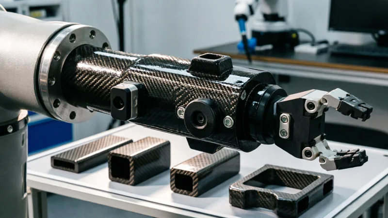
Carbon Fiber Robot End Effector Link — Custom Shape & Sensor Integration
Custom-shaped carbon fiber end effector links for robotic arms. Designed for automation integrators and research labs requiring lightweight, rigid connections between the robot wrist and gripper/tool. Can incorporate sensor mounting bosses, cable routing channels, and quick-change interfaces.

Custom Carbon Fiber Medical Device Components
Medical-grade carbon fiber components manufactured for imaging equipment, surgical instruments, and patient support systems. Carbon fiber's radiolucency (X-ray transparency) and high strength-to-weight ratio make it ideal for CT scanner beds, wheelchair frames, surgical robot arms, and MRI-compatible accessories. Biocompatible resin systems available.

Custom Carbon Fiber Musical Instrument Parts
Carbon fiber components for musical instrument manufacturing offering superior dimensional stability, low weight, and consistent acoustic properties. We produce carbon fiber bows, guitar necks, violin chin rests, drum shells, and wind instrument bodies. Carbon fiber instruments are immune to humidity changes and temperature fluctuations that affect wooden instruments.
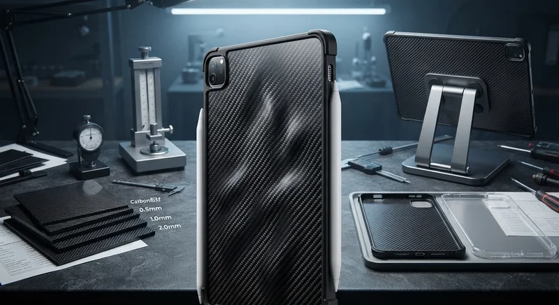
Carbon Fiber Tablet Case — Ultra-Light Protective Shell
Lightweight carbon fiber protective case for tablets and iPads. Molded from T700 3K prepreg with reinforced corner protection. Adds minimal weight while providing superior rigidity and drop protection compared to polycarbonate or silicone cases. Ideal for field workers, enterprise deployments, and professionals requiring durable tablet protection.