
Automated fiber placement (AFP) is how the aerospace industry builds today's largest carbon fiber structures — wing skins, fuselage barrels, and launch vehicle fairings. A modern AFP cell can place hundreds of kilograms of carbon fiber tow per shift, yet its true throughput is decided n
Introduction
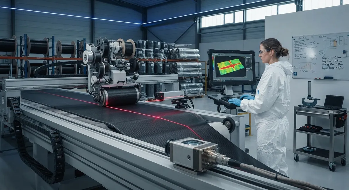
Automated fiber placement (AFP) is how the aerospace industry builds today's largest carbon fiber structures — wing skins, fuselage barrels, and launch vehicle fairings. A modern AFP cell can place hundreds of kilograms of carbon fiber tow per shift, yet its true throughput is decided not by placement speed but by how much of that material ends up inside the defect limit. Gaps, overlaps, twisted tows, and bridging have historically been caught only after the layup is complete, during ultrasonic inspection — by which point rework means removing material, not adding it. Inline defect detection for AFP closes that loop by putting inspection directly into the placement process, and it is changing the economics of large-structure composite manufacturing.
This article covers the defect types that matter in AFP, the optical sensor technologies now used to detect them in line, the tolerance limits that drive acceptance decisions, and the data-driven correction loops that turn a placement head into a closed-loop system. For process engineers and program managers, the practical question is which inspection approach to standardize on — and how to size it for the defect rates their program actually sees.
What Defects Actually Occur in AFP
AFP defects fall into a small number of repeatable categories. Gaps are narrow bands of exposed substrate between adjacent courses; overlaps are regions where one course rides over its neighbor. Tow twists and gaps within a course (individual tow wander) appear when steering tension is mis-set. Bridging occurs when tows fail to conform into concave features, and fiber pickup or FOD (foreign object debris) happens when tack is wrong or tooling is contaminated.
Not all defects are equal. A small gap in a lightly loaded region may be fully acceptable, while the same gap on a highly loaded ply edge can trigger rejection. That is why acceptance is driven by tolerance limits defined at the part level, not by a single global rule. The table below summarizes the common defects and their typical acceptance windows in aerospace practice:
| Defect | Typical Aerospace Tolerance | Primary Cause | Impact on Part |
|---|---|---|---|
| Inter-course gap | 0-2.5 mm wide, limits per ply | Course steering, head tracking error | Local strength knockdown; matrix-rich zone |
| Overlap | 0-1.0 mm typical | Course spacing error, layup path | Thickness build-up; porosity risk |
| Tow twist (180°) | Reject — repair or rework | Creel tension, payout error | Broken load path; wrinkle |
| Tow gap within course | 0-3 mm, count limited | Tow wander, compaction uneven | Minor strength knockdown |
| Bridging over concave features | Reject if radius-critical | Insufficient compaction force | Void at radius; delamination risk |
| Fiber pickup / FOD | Zero tolerance | Tack, contamination, roller wear | Porosity; hidden delamination |
The tolerance column matters because it defines what an inline system must be able to measure. A sensor that resolves features at 1 mm is sufficient for gap and overlap control; catching tow twists and FOD reliably requires either higher resolution or a complementary sensing mode.
Optical Sensing Options for Inline Inspection
Three optical approaches dominate current inline AFP inspection systems, and they are increasingly combined rather than chosen against each other:
- Laser line (profile) scanners — project a laser line across the laid course and reconstruct a 3D height profile. They directly measure gap width, overlap height, and step geometry with sub-millimeter accuracy at placement speeds, and are the workhorse for gap/overlap metrics.
- Structured-light / stereo camera systems — capture 2D imagery plus depth from multiple views, enabling detection of tow twists, fiber angles, and surface texture anomalies. They add slower but richer data suitable for defect classification.
- Thermal (IR) imaging — used mainly for thermoplastic in-situ consolidation, where the thermal signature at the nip point reveals consolidation quality, voids, and temperature uniformity that visible light cannot see.
Optical sensors are mounted on or near the placement head so inspection happens immediately after compaction, while the material is still indexed to the head frame. Typical mounting locations include the trailing edge of the compaction roller and a short distance ahead of the nip point for pre-lay inspection of the substrate.
Resolution, Speed, and Data Volume
The engineering constraint in inline AFP inspection is not sensor capability but data throughput. A head placing six 6.35 mm tows at 20 m/min creates roughly 300 meters of laid tow per minute, and a line scanner sampling at several kilohertz produces millions of profile points per course. The system must classify each point as good, gap, overlap, twist, or bridge before the next course starts — otherwise the correction decision arrives too late.
Real systems balance this with a tiered pipeline: high-speed line scanning for geometry metrics, triggered structured-light capture for classification of anomalies flagged by the scanner, and offline machine-learning models that learn defect signatures from accumulated production data. Reported detection rates in production AFP cells range from 0.5-2.0 mm minimum feature size at placement speeds of 5-20 m/min, with false-positive rates low enough to avoid flooding the corrective queue.
Data-Driven Correction: From Inspection to Closed-Loop
Inline detection only pays off if the data drives action. The evolution is happening in three stages:
- Stage 1 — Post-course alerts: the system flags defects with coordinates and severity; an operator reviews and decides on manual repair or accepted-with-disposition. This already eliminates blind spots and speeds up disposition decisions.
- Stage 2 — Adaptive process parameters: the controller uses measured gap/overlap trends to adjust course spacing, compaction force, or head speed in real time, reducing defect incidence rather than just reporting it.
- Stage 3 — Predictive correction: machine-learning models correlate defect signatures with upstream settings (creel tension, tow path, temperature), enabling preemptive adjustment before a defect pattern establishes.
Programs implementing stages 1 and 2 typically report first-pass yield improvements of 10-30% on complex contoured parts, with rework hours shifting from post-cure inspection to in-process correction. The key enabler is that every laid course becomes a digital record — a per-tow map of geometry and quality that flows into the part's digital twin and, ultimately, its certification documentation.
Frequently Asked Questions
What is the minimum defect size an inline AFP optical system can detect?
Production inline systems typically resolve features down to 0.5-1.0 mm in width using laser profile scanning at placement speeds of 5-20 m/min. Detection of tow twists, which are more of a pattern anomaly than a geometry step, is usually handled by structured-light or stereo camera capture triggered when the scanner flags a suspicious profile. The practical limit is set more by data throughput and defect classification latency than by raw sensor resolution.
How do gap and overlap tolerances affect acceptance decisions?
Acceptance is part-level, not global. Most aerospace programs allow inter-course gaps up to roughly 2.5 mm wide with per-ply limits on total gap area, while overlaps are typically held to 1.0 mm or less because they add thickness that can cause porosity or interfere with adjacent plies. Critical features such as ply edges, radii, and splice zones carry tighter windows. The inline system's job is to measure every feature against these defined windows so disposition decisions are consistent and auditable.
Can inline inspection eliminate post-cure ultrasonic NDT?
Not yet, and most programs do not expect it to. Inline optical inspection catches surface and near-surface geometry defects at layup time, which eliminates a large share of rework that would otherwise only surface at final NDT. However, ultrasonic inspection still verifies internal quality — voids, delaminations, and porosity that no surface sensor can see. The realistic target is a dramatic reduction in rework and a tighter first-pass-yield, not the removal of final NDT.
Does inline inspection work for thermoplastic AFP with in-situ consolidation?
Yes, and it is especially valuable there. Thermoplastic AFP consolidates as it lays, so defects are effectively locked in the moment they are created — there is no later autoclave step that might heal or mask them. Thermal imaging at the nip point adds a consolidation-quality channel (temperature uniformity, void signature) that visible-light geometry sensing cannot provide, which is why production thermoplastic cells frequently pair a line scanner with an IR camera.
Conclusion
Inline defect detection is moving AFP from a blind placement process to a measured one. Laser profile scanning gives fast, accurate gap and overlap geometry; structured-light and thermal channels add classification and consolidation insight; and the tiered data pipeline turns raw measurements into per-tow digital records that drive correction and certification. The result is higher first-pass yield, less post-cure rework, and a dataset that continuously improves the process.
For programs evaluating AFP — whether aerospace, energy, or marine — the inspection strategy should be decided together with the placement cell, not bolted on afterward. Review our carbon fiber tow, prepreg, and reinforcement range, or talk to our engineering team about material specifications and process integration for your next program.
Part of topic
Related Articles
- Carbon Fiber Drone Blades and Propellers: Stiffness, Balance and Noise Reduction
- Fiberglass Filament Wound Tubes: Cost-Effective Alternative to Carbon Fiber
- Filament Wound Epoxy Tube Design: Wall Thickness, Fiber Angle and Load Optimization
- Filament Wound Epoxy Tubes: Testing Standards and Quality Assurance
- Filament Wound Epoxy Tubes Manufacturing: Process and Quality Control
- Filament Wound Fiberglass Tube: Process Parameters and Performance vs Carbon Fiber
Interested in Our Products?
Contact our team for competitive pricing and technical specifications.
Get a QuoteRelated Products

Carbon fiber standard plate-3k stripe
Lightweight, ultra-rigid standard sheets for drone fuselages, robot housings, facades and structural applications.

Carbon Fiber Plate — 3K Twill T700 3.0mm
Medium-thickness 3.0mm carbon fiber plate offering significantly higher load capacity while maintaining attractive 3K twill finish. Suitable for structural brackets, reinforcement plates, and load-bearing panels.

Carbon Fiber Plate — 3K Twill T700 1.5mm
Thin 1.5mm carbon fiber plate with 3K twill weave surface. Lightweight and stiff, commonly used for covers, panels, drone bodies, and applications requiring a premium aesthetic appearance.

Custom Carbon Fiber Medical Device Components
Medical-grade carbon fiber components manufactured for imaging equipment, surgical instruments, and patient support systems. Carbon fiber's radiolucency (X-ray transparency) and high strength-to-weight ratio make it ideal for CT scanner beds, wheelchair frames, surgical robot arms, and MRI-compatible accessories. Biocompatible resin systems available.

Square Carbon Fiber Tube — 3K Twill T700
Square cross-section carbon fiber tube manufactured with 3K twill weave for torsional strength. Preferred for structural frames, trusses, and support columns where rectangular geometry offers design flexibility.