
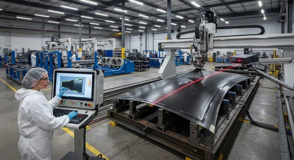
Automated fiber placement has become the workhorse for large carbon fiber structures — wing skins, fuselage barrels, wind turbine spar caps and rocket motor cases — because it deposits narrow tows at speeds and repeatability that hand layup cannot match. A single head places several tow
Introduction
Automated fiber placement has become the workhorse for large carbon fiber structures — wing skins, fuselage barrels, wind turbine spar caps and rocket motor cases — because it deposits narrow tows at speeds and repeatability that hand layup cannot match. A single head places several tows at once, at speeds past 30 m/min. But the same automation creates a new inspection burden: defects are introduced fast, and if they are not caught while the ply is being laid, they are buried under subsequent plies and become expensive to find and impossible to repair without grinding.
The defect family that dominates AFP quality discussions is small and well understood: gaps between adjacent tows, overlaps where tows touch, and wrinkles that form when a tow is steered or settled unevenly. The industry has learned that complete defect prevention is rarely economical. The practical question is detection speed and disposition discipline — knowing which defects are acceptable, which must be repaired, and which require the part to be scrapped. This article walks through the defect mechanisms, the two main online sensing routes, and a disposition logic that production shops can implement today.
The Defect Spectrum in Automated Fiber Placement
AFP defects fall into four groups, each with a distinct formation mechanism and a distinct mechanical consequence. Understanding the mechanism matters because the detection method and the repair route both depend on it:
| Defect | Formation Mechanism | Typical Severity | Primary Consequence |
|---|---|---|---|
| Gap | Tow trajectory error, compaction roller roller skip, software offset | 0.5-3 mm wide | Resin-rich zone, reduced local modulus, porosity path |
| Overlap | Tow width variation, course offset, steering compression | 0.5-2 mm | Fiber-rich zone, thickness build-up, waviness initiation |
| Wrinkle (out-of-plane) | Steering radius too tight, tack mismatch, compaction anomaly | 0.1-2 mm amplitude | Compressive strength knockdown, delamination embryo |
| Gap between tows in one course | Mixture of the above | Variable | Same as gap, aggravated by subsequent ply bridging |
Gaps and overlaps are planar defects: they lie in the ply plane and mainly disturb the local fiber volume fraction. Wrinkles are out-of-plane defects and are far more dangerous because they create an initial waviness that acts as a stress raiser under compression, which is the dominant load case for most stiffened panels. A wrinkle amplitude of even 0.5 mm can knock 20-30 percent off the compressive strength of a heavily loaded laminate, whereas a well-bounded gap of the same width is often tolerated by design allowables.
Why Gaps, Overlaps and Wrinkles Matter
The mechanical penalty is not uniform. In a gap, the adjacent tows do not cover the full course width, so a resin-rich pocket forms where the material is softer and more prone to microcracking. In aerospace allowables, gaps within an agreed width band (typically up to 3 mm for gage plies and 1 mm for structural plies) are accepted if they are separated by a minimum distance; overlapping gaps are not, because the two resin pockets merge into a zone that no longer carries load coherently. Overlaps create the reverse problem — a fiber-rich hump that locally raises the thickness, stresses the neighboring plies, and can feed waviness into the next course laid on top of it.
Wrinkles concentrate the discussion because they convert a manufacturing anomaly into a structural one. A wrinkle is a buckle of the tow stack that lifts fibers out of the plane; under compression, that pre-buckle becomes the site where the laminate fails first. The sensitivity is steep: a 1 percent out-of-plane waviness ratio can reduce compression strength by 15-25 percent in unidirectional material, and the penalty grows as the layup ratio of 0-degree plies rises. This is why wrinkle disposition is the strictest of the three: wrinkles above a design threshold are not repaired by filling — the affected region must be removed and re-laid or the part rejected.
Online Detection: Laser Line Scanning and Thermal Imaging
Two sensing families dominate in-process AFP inspection, and they are complementary rather than competing. Laser line scanning projects a structured light stripe ahead of or behind the compaction roller and reconstructs the surface topography; it resolves in-plane gaps and overlaps at sub-millimeter resolution and catches thickness steps introduced by overlaps. Thermal imaging watches the heat signature at the nip point or along the newly placed tows and detects anomalies in contact and consolidation — for example, a tow that is not compacted evenly appears as a cold zone because the air gap blocks heat transfer. The table below compares the routes:
| Capability | Laser Line Scan | Thermal Imaging |
|---|---|---|
| Primary detection | Gaps, overlaps, thickness steps | Consolidation anomalies, porosity, adhesion defects |
| Lateral resolution | 0.1-0.5 mm typical | 1-5 mm typical |
| Inspection speed | Full-width at placement speed | Full-width at placement speed |
| Wrinkle sensitivity | Good at moderate amplitude | Indirect, via consolidation |
| Data output | Topography map per course | Thermal map per course |
| Typical use | Immediate disposition of gaps/overlaps | Consolidation and tack quality trending |
In a modern integrated cell, the two are combined: the laser scanner performs the accept-reject decision on gaps and overlaps course by course, while the thermal camera feeds a quality trend that flags compaction drift before defects grow large enough to be caught topographically. The key advantage of online detection over post-layup ultrasonic inspection is the ability to act while the ply is still accessible — a defect detected at course N can be repaired before course N+1 buries it.
Disposition Logic: Accept, Repair or Reject
An effective AFP cell runs a three-bucket disposition logic that is fixed before the program starts, because improvisation at the machine produces inconsistency and scrap. The standard framework is:
- Accept within allowables: Gaps and overlaps inside the width band, separated by the minimum distance, and wrinkles below the amplitude threshold are signed off as-is. This is where design allowables and the inspection threshold must be aligned; overly tight thresholds create needless repairs and rework labor.
- Repair on the fly: Isolated gaps and overlaps beyond the band are repaired immediately — by re-laying the faulty course, filling the gap with a narrow tow, or adding a locally patched ply — as long as the fix is completed before the next ply covers the region.
- Reject and re-lay: Wrinkles above the threshold, overlapping gaps, and any defect that repeats in the same zone across multiple courses trigger course removal or full re-lay of the affected area. Rejection is also the default when repair would add more material than the layup was designed to carry.
A well-run program reviews the actual defect statistics monthly and tunes the thresholds against mechanical test data rather than leaving them as engineering judgment.
Repair Strategies for Placement Defects
When a defect is dispositioned for repair, the method depends on when it is found and what type it is. For gaps found immediately after the course is laid, the fastest repair is a hand-laid narrow tow strip or a short re-placement pass of the same course, both of which keep the ply surface planar. For overlaps, the tow is either lifted and re-positioned if still tacky, or the excess material is sanded flush under controlled conditions before cure — a route that must be validated because sanding a fiber-rich hump can damage neighboring tows. Wrinkles found late, after several plies are down, are the most expensive: the region must be removed by grinding or routing down to the wrinkled ply, rebuilt with hand-laid patches and filler, and then inspected again. Many programs instead disposition repeated wrinkles as a machine-learning input — the AFP program is adjusted, or the tack and compaction parameters are changed, so the defect stops occurring rather than being repaired after the fact.
The trend in large-scale production is to make repairs rarer by feeding defect statistics back into process control. Deposition speed, roller pressure, and tow tension are adjusted continuously from the thermal trending data; software offset corrections from the laser scanner are applied to subsequent courses automatically. This closed-loop behavior is one of the strongest cost levers in modern AFP, and it is a measurable difference between mature programs and first-generation installations.
Production Implications and First-Pass Yield
First-pass yield is the number that ties all of this together. A typical AFP cell running without online inspection reports effective yield losses of 5-15 percent from undetected gaps, overlaps and wrinkles that surface at ultrasonic inspection, at which point rework is grinding-heavy and schedule-expensive. The same cell with an integrated laser scan and thermal imaging stack typically sees those defects either prevented by process feedback or repaired in seconds at the course level, pushing first-pass yield toward 95-99 percent. Because AFP deposition rates are high, the inspection infrastructure — not the placement head — is often the throughput bottleneck.
For buyers specifying AFP-produced parts, the quality discussion should therefore start with the inspection equipment and disposition rules, not with the machine's deposition rate. A qualified supplier can show course-level inspection records, disposition thresholds with documented rationale, and repair procedures validated by mechanical test coupons. These records are the difference between a supplier who controls defects and one who discovers them.
Frequently Asked Questions
What is the difference between a gap and an overlap in AFP?
A gap is a space between adjacent tows where the laminate surface is not covered, leaving a resin-rich pocket; an overlap is where two tows touch or ride over each other, creating a fiber-rich hump. Both are planar defects. Gaps weaken the local modulus and invite porosity, overlaps build thickness and can initiate waviness in subsequent plies. Neither is automatically rejected — both fall under width-band allowables and separation-distance rules defined by the design.
Can AFP wrinkles be repaired, or must the part be scrapped?
It depends on the amplitude and the load case. Small wrinkles within the design threshold are accepted as manufactured. Larger wrinkles found before burial by subsequent plies can be removed and the affected course re-laid, which is fast. Wrinkles found after several plies are down require grinding out the region, patching and re-consolidating, followed by full re-inspection — an expensive route that many programs avoid by detecting the defect online and adjusting compaction parameters before it recurs.
Why is thermal imaging useful in AFP if it cannot measure gaps directly?
Thermal imaging measures consolidation quality rather than geometry. A tow that is not compacted evenly against the substrate shows a different heat signature at the nip point because trapped air blocks heat conduction. That signal reveals tack mismatch, roller pressure drift and incipient porosity before they become visible as gaps or wrinkles. Running laser scanning for geometry and thermal imaging for consolidation is the standard combined configuration in modern integrated AFP cells.
Conclusion
Automated fiber placement is a high-speed process whose quality is decided by the speed and discipline of defect disposition. Gaps, overlaps and wrinkles form for identifiable reasons, are detectable in process with laser line scanning and thermal imaging, and are manageable with a fixed accept-repair-reject logic that aligns inspection thresholds with design allowables. The engineering effort goes into connecting the sensor data to the disposition decision and feeding the statistics back into process control, so that defects are prevented rather than repaired. For programs still treating gaps and wrinkles as something found at ultrasonic inspection, the yield penalty is structural, not cosmetic.
YongXian supplies carbon fiber tow, unidirectional and multiaxial fabrics, and prepreg systems used in AFP programs across aerospace, wind energy and automotive applications. Explore our carbon fiber product range or contact our engineering team to discuss tow specifications, tack requirements and inspection-friendly material formats for your placement process.
Related Articles
- Bio-Based Carbon Fiber Precursors: Lignin and Polyethylene for Low-Cost Production
- Large-Tow Carbon Fiber Cost Analysis: 48K vs 60K Price-Performance Comparison
- Carbon Fiber-Resin Interface Bonding: Surface Treatment and Coupling Agent Optimization
- Digital Twin for Carbon Fiber Manufacturing: Real-Time Process Monitoring and Defect Prevention
- Thermoplastic Carbon Fiber Welding for Automotive: Ultrasonic and Induction Welding Process Windows
- Large-Tow Carbon Fiber Wet Spinning: Process Optimization for 48K/60K Production Efficiency
Interested in Our Products?
Contact our team for competitive pricing and technical specifications.
Get a QuoteRelated Products

Carbon Fiber Fishing Rod Blank
High-quality carbon fiber fishing rod blank manufactured from multiple grades of Toray carbon fiber cloth. Available in a wide range of lengths, powers, and actions for freshwater and saltwater applications. Suitable for OEM rod building.

Carbon Fiber Plate — 3K Twill T700 3.0mm
Medium-thickness 3.0mm carbon fiber plate offering significantly higher load capacity while maintaining attractive 3K twill finish. Suitable for structural brackets, reinforcement plates, and load-bearing panels.

Carbon Fiber Plate — 3K Twill T700 1.5mm
Thin 1.5mm carbon fiber plate with 3K twill weave surface. Lightweight and stiff, commonly used for covers, panels, drone bodies, and applications requiring a premium aesthetic appearance.

Square Carbon Fiber Tube — 3K Twill T700
Square cross-section carbon fiber tube manufactured with 3K twill weave for torsional strength. Preferred for structural frames, trusses, and support columns where rectangular geometry offers design flexibility.
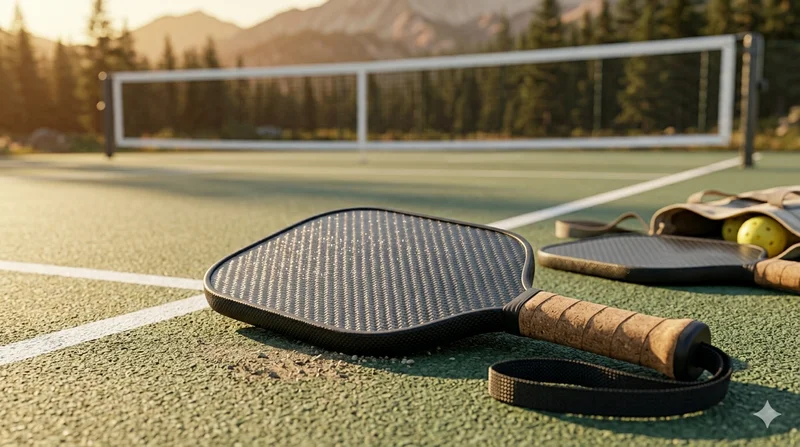
Carbon Fiber Pickleball Paddle
High-performance pickleball paddle with Toray T700 carbon fiber face and polypropylene honeycomb core. Delivers excellent power-to-weight ratio, spin generation, and vibration dampening for competitive play.