
Liquid hydrogen stores three times more energy per unit volume than compressed hydrogen, which is why every serious program for hydrogen-powered aircraft is converging on cryogenic LH2 storage. But the tank that holds it must operate at −253°C — the boiling point of liquid hydrogen — wh
Introduction
Liquid hydrogen stores three times more energy per unit volume than compressed hydrogen, which is why every serious program for hydrogen-powered aircraft is converging on cryogenic LH2 storage. But the tank that holds it must operate at −253°C — the boiling point of liquid hydrogen — where carbon fiber composites behave differently from their room-temperature design data: the matrix becomes brittle, thermal strains accumulate across the wall, and microcracks open pathways for the smallest molecule in existence to escape.
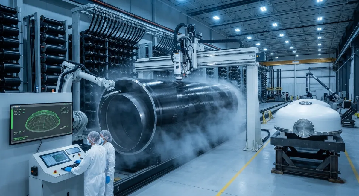
Automated fiber placement (AFP) has become a leading candidate for building these tanks because it combines the geometric freedom of tow-steered layup with the repeatability and low porosity that a cryogenic pressure boundary demands. A European industry consortium has been advancing composite LH2 tank demonstrators for commercial aircraft — combining AFP with hybrid filament winding, welding of thermoplastic components, and integrated SHM and hydrogen sensing — with demonstration flights targeted for the coming years. This article explains the placement strategies behind these tanks, the material challenges at −253°C, and how AFP fits into the broader manufacturing picture.
The Cryogenic Materials Challenge
At −253°C, the failure modes of a composite tank wall are different from those at room temperature:
- Matrix embrittlement and microcracking: Epoxy matrices contract and stiffen dramatically at cryogenic temperature. The mismatch between the low coefficient of thermal expansion (CTE) of the fibers and the much higher CTE of the matrix generates thermal stresses that crack the matrix, producing microcracks in plies not aligned with the load direction.
- Hydrogen permeability: Molecular hydrogen is small enough to pass through a cracked matrix. Even with a liner, microcracks in the load-bearing wall can migrate into the liner over cycling and degrade it, so the wall itself must be designed to resist cracking — not just the liner.
- Thermal cycling damage: Every fill and drain cycle of the tank — from ambient to −253°C and back — adds damage. The number of cycles a tank must survive over its operating life drives the microcrack tolerance and therefore the laminate design.
These constraints push the design toward crack-resistant laminate architectures: fiber-dominated layups, toughened matrix systems, thin-ply materials, and careful control of ply blocking and residual stress through the wall thickness.
AFP Placement Strategies for LH2 Tank Walls
AFP brings specific advantages to the cryogenic tank problem. The table below compares the main manufacturing routes for composite LH2 tank walls:
| Manufacturing route | Placement precision | Microcrack resistance | Geometric freedom | Production rate |
|---|---|---|---|---|
| AFP (tow steering) | High — steered fiber angles, local ply drops | High with thin plies and toughened resin | High — crowns, domes, local build-ups | Moderate |
| Filament winding (helical + hoop) | Moderate — geodesic paths only | High, well established for pressure vessels | Limited — cylindrical bodies, smooth domes | High |
| Hybrid AFP + winding | High in AFP zones, winding for hoop layers | High — optimized per zone | High — AFP handles geometry, winding adds speed | Moderate-high |
| Thermoplastic AFP (in-situ consolidation) | High — welded, no autoclave | Very high with toughened TP matrices | High | High (no cure step) |
Three placement strategies matter most for cryogenic performance. First, tow steering and ply blocking control: AFP steers tows to follow load paths and avoids the thick ply blocks that concentrate thermal stress, using thin plies (30-80 g/m² areal weight) to distribute strain and delay microcrack onset. Second, local build-up and ply drops: tank wall thickness varies from pole to equator — thicker at the bosses and transitions where loads concentrate — and AFP drops and adds plies locally without cutting the fiber at sharp angles. Third, path planning for low porosity: cryogenic pressure boundaries fail at microcracks and voids; AFP's compaction, heated placement, and process control achieve the low void content (below 1%) that a leak-tight wall requires, with process monitoring feeding porosity prediction.
Liner, Wall, and Insulation Architecture
A practical LH2 tank is not a single material — it is a layered pressure boundary. The architecture of a representative aerospace tank combines several functions:
- Cryogenic liner: Either a thin metal liner (welded aluminum or stainless steel, about 1-2 mm) that forms the primary hydrogen barrier, or a polymer liner in a linerless design where the composite wall itself must be microcrack-tolerant enough to be the barrier.
- AFP composite wall: The load-bearing laminate — typically 15-40 mm thick at the cylindrical section for an aircraft-scale tank — built with the placement strategies described above, carrying the internal pressure at −253°C and the mechanical loads of the airframe.
- Insulation: Because LH2 boils at −253°C, the tank must be insulated against ambient heat leak, typically with multi-layer insulation (MLI) blankets or foam. The insulation is outside the load-bearing wall, where it does not carry structural load.
- Integrated sensing: The consortium demonstrators embed SHM sensors and hydrogen sensors into the wall or at its surface, providing continuous leak and strain monitoring for certification and in-service safety.
This layered design creates the AFP-specific challenge of manufacturing a thick, crack-resistant wall around a liner without damaging either: the liner must survive the placement and consolidation loads, and the wall must be built with a thermal and strain history that the design assumes.
Qualification and Testing for Cryogenic Service
Certifying an AFP-built LH2 tank requires test evidence beyond conventional pressure vessel qualification:
- Cryogenic burst and cycle testing: Tanks are pressurized and cycled at −253°C with liquid hydrogen or liquid nitrogen (LN2, −196°C) as a conservative substitute, demonstrating burst pressure margins and cycle life with leak measurement after every cycle.
- Permeability testing: Helium leak testing is the standard method for measuring hydrogen-scale leak rates through the wall and liner, with acceptance criteria in the 10⁻⁷ to 10⁻⁹ mbar·L/s range depending on the design.
- Microcrack inspection: Ultrasonic and X-ray CT inspection at cryogenic temperature — or after cryogenic cycling at room temperature — quantifies microcrack density in the wall and verifies it stays below the design limit.
- Process qualification: AFP process parameters — placement temperature, compaction force, tow tension, and void content — are locked through the same materials and process qualification framework used for airframe composites, extended for cryogenic exposure.
Frequently Asked Questions
Why is AFP preferred over pure filament winding for cryogenic LH2 tanks?
Filament winding follows geodesic paths — the natural, shortest routes on a surface — which limits where fiber angles can be placed and makes it difficult to build local thickness variations, ply drops, and steering around bosses and transitions. AFP places individual tows under CNC control, so fiber angles can be steered to follow load paths, thickness can be built up locally where the tank is heavily loaded, and cuts and restarts happen anywhere on the surface. For a cryogenic tank, this geometry freedom directly serves microcrack resistance: load-aligned, thin-ply laminates without thick ply blocks crack far less under thermal cycling. In practice the two are often combined — AFP for the crown, dome, and transition zones where geometry and loads are complex, filament winding for the long cylindrical section where straight hoop and helical paths are efficient and proven.
How does thermoplastic AFP differ from thermoset AFP for cryogenic tanks?
Thermoset AFP places uncured prepreg tows that must be cured in an autoclave or oven, with the layup and cure as separate steps. Thermoplastic AFP consolidates each tow in situ — heated, compacted, and welded as it is placed — so the wall is built and consolidated in one step with no autoclave. For cryogenic tanks, thermoplastic matrices (such as low-melt polyaryletherketone, PAEK-family resins) have two advantages: their inherently higher fracture toughness delays microcrack onset at −253°C, and welding enables joining tank sections or attaching bosses without adhesive or fastener lines that could become leak paths. The trade-offs are higher material cost, higher processing temperatures, and less accumulated flight heritage. Several programs see thermoplastic AFP as the route to fast, autoclave-free LH2 tank production; the current demonstrators use a hybrid of thermoset AFP with thermoplastic elements to mature both tracks.
Can a linerless composite tank hold liquid hydrogen reliably?
Linerless tanks are the long-term goal because removing the metal liner saves weight and eliminates the liner-composite interface that can debond under thermal cycling. The requirement is demanding: the composite wall itself must achieve a microcrack density low enough that hydrogen leakage stays below acceptable limits — typically demonstrated with helium leak testing — across the full thermal cycling and pressure life of the tank. This demands thin-ply, toughened-matrix laminates built with tight porosity control, plus a continuous impermeable barrier, sometimes a thin polymer surface film co-cured into the inner wall. Today, most flight programs still fly metal-lined tanks as the certified configuration, while linerless designs are validated on ground and subscale demonstrators. AFP's porosity control and thin-ply capability are precisely the tools that make linerless tanks feasible.
Conclusion
AFP is moving from a promising process to the enabling technology for cryogenic liquid hydrogen storage in aerospace. The combination of tow steering, thin-ply crack-resistant laminates, local build-up, and low porosity addresses the core problem of LH2 tanks — holding pressure and preventing leakage at −253°C through hundreds of thermal cycles. The European demonstrator programs pairing AFP with hybrid winding, welding, and integrated sensing are producing the data that will certify the first composite LH2 tank for commercial aircraft.
For engineers and buyers evaluating tank manufacturing routes, the practical decisions are placement strategy, liner architecture, matrix system, and qualification scope. Explore our carbon fiber materials for pressure vessel and cryogenic applications, or contact our engineering team to discuss material selection, AFP tow specification, and qualification support for your LH2 tank program.
Part of topic
Related Articles
- Carbon Fiber Drone Blades and Propellers: Stiffness, Balance and Noise Reduction
- Fiberglass Filament Wound Tubes: Cost-Effective Alternative to Carbon Fiber
- Filament Wound Epoxy Tube Design: Wall Thickness, Fiber Angle and Load Optimization
- Filament Wound Epoxy Tubes: Testing Standards and Quality Assurance
- Filament Wound Epoxy Tubes Manufacturing: Process and Quality Control
- Filament Wound Fiberglass Tube: Process Parameters and Performance vs Carbon Fiber
Interested in Custom Carbon Fiber Products?
Contact our team for competitive pricing and technical specifications.
Get a QuoteRelated Products

Carbon Fiber Fishing Rod Blank
High-quality carbon fiber fishing rod blank manufactured from multiple grades of Toray carbon fiber cloth. Available in a wide range of lengths, powers, and actions for freshwater and saltwater applications. Suitable for OEM rod building.
Carbon Fiber Drone Arm
Precision-molded carbon fiber drone arm combining unidirectional fiber for stiffness and woven layers for torsional strength. Designed for FPV, photography, and industrial drone platforms. Each arm is CNC-machined to exact specifications.