
Laminated composites are strong in their plane and weak through their thickness. When an impact loads a carbon fiber laminate — a dropped tool, runway debris, a blast fragment — the energy propagates as delamination cracks between plies, where only the resin matrix resists. This single
Introduction
Laminated composites are strong in their plane and weak through their thickness. When an impact loads a carbon fiber laminate — a dropped tool, runway debris, a blast fragment — the energy propagates as delamination cracks between plies, where only the resin matrix resists. This single weakness drives design allowables down, forces thicker laminates, and sets the inspection and repair intervals that aerospace operators watch closely. Through-thickness reinforcement changes the picture by placing fibers in the Z direction, physically stitching or weaving the layers together so that cracks cannot run freely between them.
Four industrial methods deliver this reinforcement: 3D weaving integrates Z-binder yarns into the fabric itself, tufting and stitching insert threads into dry preform stacks, and z-pinning pushes rigid pins into laminates. All four improve interlaminar toughness and impact damage tolerance, and all four impose a small in-plane penalty. This article compares the methods, quantifies the impact tolerance gains — compression-after-impact strength improves by 30-50% — and examines the fan case, armor, and marine applications where that margin decides whether a structure survives an impact.
Why Delamination Governs Design
Impacts create matrix cracks and delaminations even when no fiber damage is visible on the surface. The engineering consequence is that compression-after-impact (CAI) strength — the residual compression strength of a laminate after a standardized impact — becomes the design-limiting property rather than pristine strength. Typical aerospace carbon fiber laminates retain only 35-50% of their compression strength after a low-energy impact; that loss forces designers to thicken panels and add doublers. Through-thickness reinforcement raises the CAI retention floor because the Z-fibers arrest delamination growth: cracks must break fibers or deviate around them, consuming far more energy per millimeter of growth.
Through-Thickness Reinforcement Methods Compared
The four industrial methods differ in when they act, how much Z-fiber they add, and what they cost in in-plane properties:
| Method | Stage of process | Z-fiber form | In-plane penalty | Automation | Best suited to |
|---|---|---|---|---|---|
| 3D weaving | Fabric production | Integrated binder yarns | 10-15% tensile loss | Jacquard looms | Near-net-shape preforms |
| Tufting | Dry preform | Carbon or aramid thread loops | Below 5% | Robotic, one-sided | Localized and retrofit reinforcement |
| Stitching | Dry preform | Through-thickness thread seams | 5-10% | Sewing heads | Large panels, thick laminates |
| Z-pinning | Cured or uncured laminate | Metal or carbon pins | About 5% | Ultrasonic insertion | Retrofit and local reinforcement |
3D weaving places the reinforcement at the textile stage, producing a homogeneous architecture with no post-processing, which is why it suits complex near-net-shape parts such as fan blades and fittings. Tufting and stitching work on dry fabric stacks that already exist, making them compatible with established 2D fabrication lines and ideal for reinforcing only the zones that need it — for example around holes, joints, and impact-prone areas. Z-pinning operates on laminates and remains the preferred route for retrofitting or locally strengthening an existing design. For any method, the in-plane penalty is the price of the Z-fibers crimping the load-bearing layers, and it is usually small relative to the damage-tolerance gain.
Impact Tolerance: What the Z-Fibers Change
Measured outcomes are consistent across published studies. The table below shows representative values for a quasi-isotropic carbon fiber epoxy system, reinforced by 3D weaving or tufting, compared with the unreinforced baseline:
| Property | 2D laminate baseline | 3D woven | Tufted laminate | Improvement |
|---|---|---|---|---|
| CAI strength retention | 35-50% | 60-75% | 55-70% | +30-50% |
| Delamination area after impact | Baseline | 30-50% smaller | 20-40% smaller | Reduced |
| Mode I fracture toughness (J/m²) | 200-350 | 500-700 | 400-600 | 1.5-2.0x |
| Mode II fracture toughness (J/m²) | 800-1,200 | 1,200-1,600 | 1,000-1,400 | 1.3-1.5x |
The mechanisms behind these numbers are straightforward. Z-fibers bridge the crack plane, so a crack growing between plies must tear or pull out the reinforcement, absorbing energy that an unreinforced laminate spends on pure propagation. This bridging effect also distributes impact energy over a wider area, shrinking the delamination footprint and delaying the transition from delamination to fiber failure. For containment and armor structures, the same physics translates into higher energy absorption per unit mass before catastrophic failure.
Tufting in Practice
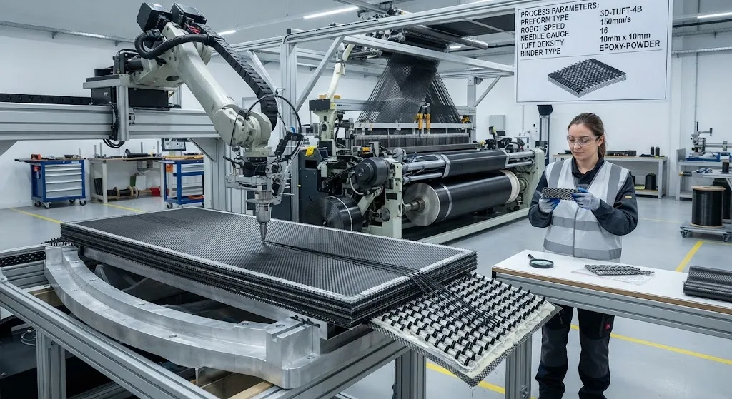
Tufting has become the fastest-growing option for producers who already run 2D dry-fiber lines. A robotic head drives a hollow needle through a dry fabric stack, inserting a carbon or aramid thread that forms a loop on the opposite surface; the needle withdraws and moves to the next point at rates of 1-5 stitches per second. Because the needle approaches from one side only, tufting works on curved and double-curved preforms without a backing tool, and the stack is consolidated afterward by resin transfer molding or infusion — the inserted threads become part of the final structure. The practical advantages are flexibility in placement, near-zero tooling, and the ability to reinforce specific zones rather than the whole part. The trade-offs are that the surface loops affect finish, and the process adds a production step for parts that could otherwise be woven integrally.
Impact-Critical Applications
Applications that specify through-thickness reinforcement cluster where impact energy is high and consequences are severe:
- Engine fan cases and containment: 3D woven preforms contain blade-out events, with the Z-reinforcement preventing the large-scale delamination that could let debris escape the casing.
- Armor and ballistic structures: Vehicle and personnel protection panels use tufted or woven aramid/carbon systems; the 30-50% higher CAI translates directly into multi-hit capability and reduced back-face deformation.
- Marine hulls and composite masts: Impact from docks, debris, and grounding loads is routine, and Z-reinforcement keeps repair costs and inspection intervals manageable.
- Wind turbine and propeller blades: Leading-edge impacts and manufacturing handling damage are contained, extending service life between inspections.
- Bolted and bonded joint regions: Localized tufting around fastener holes suppresses the delamination that typically initiates at loaded holes.
Qualification Notes
Qualifying Z-reinforced structures follows standard composite practice with two additions. First, the Z-fiber architecture must be verified nondestructively — ultrasonic testing and computed tomography must confirm binder or tuft spacing, depth, and fiber volume fraction, since a tuft that missed its target depth provides no reinforcement. Second, CAI testing per standards such as ASTM D7136 and D7137 must be run on representative thickness and curvature, because the benefit scales with laminate thickness and the failure mode shifts with stacking sequence. Suppliers should be asked for CAI retention data, delamination-area measurements, and through-thickness tensile strength values before design allowables are set.
Frequently Asked Questions
How much stronger is a tufted or 3D woven laminate after impact?
Compression-after-impact strength retention typically rises from 35-50% for a standard 2D laminate to 55-75% for a Z-reinforced one — an improvement of 30-50%. The delamination area after a given impact shrinks by 20-50%, and Mode I fracture toughness roughly doubles. The practical consequence is that a designer can meet the same damage-tolerance requirement with a thinner laminate, or keep the thickness and gain substantial extra impact margin. The improvement is not linear with the amount of Z-fiber: beyond roughly 3-5% Z-fiber volume fraction, additional reinforcement returns diminishing gains while the in-plane penalty grows, which is why most production architectures stay in that band.
What is the difference between tufting and 3D weaving?
3D weaving builds the Z-reinforcement into the fabric on the loom, using binder yarns that interlace through the thickness during textile production. The result is a homogeneous preform with no post-processing, ideal for complex near-net shapes, but it requires specialized looms and a part design that starts from the textile. Tufting adds the Z-fibers afterwards, inserting carbon or aramid threads through an already-laid dry fabric stack with a robotic needle, typically at 1-5 stitches per second. Tufting works on curved preforms, needs only one-sided access, and can reinforce selected zones instead of the whole part — which makes it the cheaper route for reinforcing established 2D production lines or adding localized reinforcement around holes and joints. The trade-off is a visible loop on one surface and an extra production step.
Does through-thickness reinforcement weaken the laminate in other directions?
Yes, there is an in-plane penalty, and it is the main design cost of Z-reinforcement. The Z-fibers crimp the load-bearing warp and weft yarns, typically reducing in-plane tensile or compressive strength by 5-15%, depending on the method: tufting is below 5%, stitching 5-10%, dense z-pinning about 5%, and full 3D weaving 10-15%. Stiffness falls less than strength because crimp affects failure earlier than modulus. Designers accept this penalty because the damage-tolerance gain is usually worth several times the in-plane loss — a laminate that survives impacts can be thinner overall, which recovers the strength deficit at the system level. Applications dominated by pure in-plane loading with no impact threat should avoid Z-reinforcement.
Conclusion
Through-thickness reinforcement converts the weakest direction of laminated composites into a hardened one. Whether the fibers arrive through 3D weaving, tufting, stitching, or z-pinning, the Z-direction links the plies together, raising CAI strength retention by 30-50%, shrinking delamination areas by up to half, and roughly doubling Mode I toughness. Each method pays a small in-plane penalty for these gains, and the choice between them is driven by part geometry, production line compatibility, and whether reinforcement is needed everywhere or only in impact-critical zones.
For engineers specifying impact-critical carbon fiber structures, the decision framework is: quantify the impact threat, compare the in-plane penalty against the CAI gain, and verify the chosen method on representative thickness. Explore our carbon fiber fabrics and 3D-capable reinforcement products, or contact our engineering team to discuss tufting, 3D weaving, or z-pinning for your structural program.
Part of topic
Related Articles
- Bio-Based Carbon Fiber Precursors: Lignin and Polyethylene for Low-Cost Production
- Large-Tow Carbon Fiber Cost Analysis: 48K vs 60K Price-Performance Comparison
- Carbon Fiber-Resin Interface Bonding: Surface Treatment and Coupling Agent Optimization
- Digital Twin for Carbon Fiber Manufacturing: Real-Time Process Monitoring and Defect Prevention
- Thermoplastic Carbon Fiber Welding for Automotive: Ultrasonic and Induction Welding Process Windows
- Large-Tow Carbon Fiber Wet Spinning: Process Optimization for 48K/60K Production Efficiency
Interested in Our Products?
Contact our team for competitive pricing and technical specifications.
Get a QuoteRelated Products

Carbon Fiber Plate — 3K Twill T700 3.0mm
Medium-thickness 3.0mm carbon fiber plate offering significantly higher load capacity while maintaining attractive 3K twill finish. Suitable for structural brackets, reinforcement plates, and load-bearing panels.
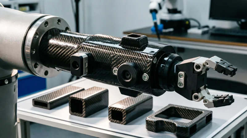
Carbon Fiber Robot End Effector Link — Custom Shape & Sensor Integration
Custom-shaped carbon fiber end effector links for robotic arms. Designed for automation integrators and research labs requiring lightweight, rigid connections between the robot wrist and gripper/tool. Can incorporate sensor mounting bosses, cable routing channels, and quick-change interfaces.

Custom Carbon Fiber Medical Device Components
Medical-grade carbon fiber components manufactured for imaging equipment, surgical instruments, and patient support systems. Carbon fiber's radiolucency (X-ray transparency) and high strength-to-weight ratio make it ideal for CT scanner beds, wheelchair frames, surgical robot arms, and MRI-compatible accessories. Biocompatible resin systems available.

Custom Carbon Fiber Musical Instrument Parts
Carbon fiber components for musical instrument manufacturing offering superior dimensional stability, low weight, and consistent acoustic properties. We produce carbon fiber bows, guitar necks, violin chin rests, drum shells, and wind instrument bodies. Carbon fiber instruments are immune to humidity changes and temperature fluctuations that affect wooden instruments.
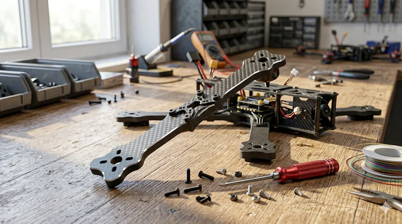
Carbon Fiber Drone Arm
Precision-molded carbon fiber drone arm combining unidirectional fiber for stiffness and woven layers for torsional strength. Designed for FPV, photography, and industrial drone platforms. Each arm is CNC-machined to exact specifications.