
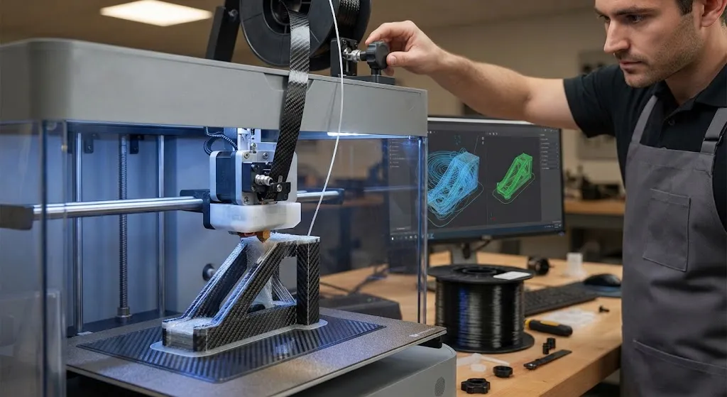
Continuous carbon fiber 3D printing has evolved from a laboratory curiosity into a viable manufacturing method for low-to-medium volume structural components. Unlike chopped-fiber-filled filaments that merely add stiffness to a thermoplastic matrix, continuous carbon fiber 3D printing l
Introduction
Continuous carbon fiber 3D printing has evolved from a laboratory curiosity into a viable manufacturing method for low-to-medium volume structural components. Unlike chopped-fiber-filled filaments that merely add stiffness to a thermoplastic matrix, continuous carbon fiber 3D printing lays down unbroken tows of real carbon fiber during the printing process, producing parts with fiber volume fractions of 30-45% and tensile strengths approaching 700 MPa. For engineers evaluating whether continuous carbon fiber 3D printing fits their production needs, understanding the FDM/FFF process parameters, material system choices, and the mechanical properties achievable today is essential.
This article examines how continuous carbon fiber 3D printing works at the process level, quantifies the mechanical properties of the resulting composites, and provides a practical comparison with traditional manufacturing methods such as prepreg-autoclave and resin transfer molding. The data and recommendations are drawn from current commercial systems and published research as of 2026.
How Continuous Carbon Fiber 3D Printing Works
In FDM/FFF continuous carbon fiber 3D printing, a dual-extrusion system feeds two materials simultaneously into a heated nozzle: a thermoplastic matrix filament (typically nylon or PEEK) and a pre-impregnated continuous carbon fiber tow. The nozzle lays down layers where the carbon fiber tow is fully embedded within the thermoplastic matrix, creating a true fiber-reinforced composite rather than a filled polymer. The key process variables that determine part quality are:
- Printing temperature: Matrix temperature must be high enough for good interlayer adhesion but not so high that it degrades the fiber-matrix interface. Typical ranges are 250-280°C for nylon-based systems and 380-420°C for PEEK-based systems.
- Bed temperature: Heated beds at 80-120°C reduce warping and improve first-layer adhesion, particularly important for parts with large footprint areas.
- Print speed: Continuous fiber printing runs slower than unfilled filament, typically 20-40 mm/s, to ensure complete impregnation of the fiber tow by the matrix. Faster speeds risk dry spots and poor fiber-matrix bonding.
- Layer height: 0.1-0.2 mm layer heights produce good consolidation. Thicker layers increase throughput but may leave interlayer voids.
- Fiber volume fraction: Controlled by the ratio of fiber tow width to layer spacing. Commercial systems achieve 30-45% fiber volume fraction, compared to 55-65% for prepreg-autoclave processes.
- Infill pattern and fiber orientation: The user defines fiber paths for each layer, enabling load-aligned reinforcement that traditional isotropic filaments cannot achieve.
Several commercial systems now offer continuous carbon fiber printing, including machines from Markforged, Anisoprint, and Desktop Health. Each uses a different approach to fiber impregnation and deposition, but all produce parts with significantly higher strength and stiffness than chopped-fiber or unfilled thermoplastic prints.
Material Systems and Their Properties
The choice of thermoplastic matrix significantly affects the mechanical performance, thermal resistance, and post-processing options of continuous carbon fiber 3D printed parts. The most common systems available today are:
| Matrix Material | Printing Temp (°C) | Tensile Strength (MPa) | Modulus (GPa) | Max Service Temp (°C) | Typical Applications |
|---|---|---|---|---|---|
| Nylon 6 (PA6) | 250-270 | 600-700 | 55-70 | 120-150 | Jigs, fixtures, functional prototypes |
| Nylon 12 (PA12) | 240-260 | 550-650 | 50-65 | 100-130 | Lightweight brackets, drone frames |
| PEEK | 380-420 | 750-900 | 70-90 | 250+ | Aerospace, high-temp tooling |
| PEKK | 360-400 | 700-850 | 65-85 | 230+ | Aerospace brackets, hot-zone fixtures |
| PPS | 300-340 | 500-650 | 50-65 | 200+ | Chemical resistance, electrical insulation |
The fiber itself is typically a standard-modulus carbon fiber tow (3K, 6K, or 12K) with tensile strength of 3,500-4,900 MPa and modulus of 230-240 GPa. The composite properties are a function of fiber volume fraction, fiber-matrix adhesion, and void content — all of which are controlled by the printing process parameters.
Mechanical Properties vs Traditional Manufacturing
The mechanical properties of continuous carbon fiber 3D printed parts fall between those of injection-molded short-fiber composites and prepreg-autoclave laminates. The table below provides a representative comparison at similar fiber volume fractions where data is available:
| Property | CF 3D Printed (PA6 matrix, 40% Vf) | Injection Molded CF (30% Vf) | Prepreg Autoclave (60% Vf) |
|---|---|---|---|
| Tensile strength (MPa) | 600-700 | 180-220 | 1,500-2,000 |
| Tensile modulus (GPa) | 55-70 | 20-25 | 120-140 |
| Flexural strength (MPa) | 700-850 | 250-300 | 1,800-2,200 |
| Interlaminar shear strength (MPa) | 35-50 | N/A (isotropic) | 80-100 |
| Impact strength (kJ/m²) | 40-60 | 8-12 | 25-40 (CAI) |
| Density (g/cm³) | 1.35-1.45 | 1.30-1.40 | 1.55-1.60 |
Continuous carbon fiber 3D printing delivers 3-4x the tensile strength and stiffness of injection-molded short-fiber parts, making it suitable for structural applications that require genuine load-bearing capability. However, it does not match prepreg-autoclave performance, primarily because fiber volume fraction is limited by the FDM deposition process and void content is typically 2-5% compared to less than 1% for autoclave-cured parts.
Design Rules and Limitations
Continuous carbon fiber 3D printing imposes several design constraints that differ from both traditional machining and conventional composite layup:
- Minimum wall thickness: Parts must be at least 1.0-1.5 mm thick to accommodate the continuous fiber tow without excessive fiber breakage at corners.
- Corner radii: Internal corners should have radii of at least 3 mm to prevent fiber crowding and resin-rich zones.
- Fiber termination: Continuous fibers cannot simply stop mid-layer; they must be routed to an edge or looped back, which affects design geometry.
- Anisotropy: Strength is highest along the fiber direction and significantly lower transverse to the fibers. Designs must account for this directional behavior.
- Post-processing: Surface finishing (sanding, coating) may be needed for Class A surfaces. CNC machining of printed parts requires diamond-coated tooling due to the abrasive carbon fiber.
Cost and Throughput Comparison
The economics of continuous carbon fiber 3D printing favor small-batch production where tooling avoidance and design iteration speed outweigh per-part material cost:
- Tooling cost: Zero for 3D printing vs $5,000-50,000 for matched-die RTM tooling and $10,000-100,000+ for autoclave tooling.
- Per-part cost: 3D printed continuous fiber parts cost $50-500 each (depending on size and material), compared to $10-100 for injection molded short-fiber parts at high volume and $200-2,000 for prepreg-autoclave at low volume.
- Lead time: 3D printing: 2-8 hours from design to part. Injection molding: 4-12 weeks for tooling, then minutes per part. RTM: 2-6 weeks for tooling, then 1-4 hours per part.
- Break-even volume: Continuous fiber 3D printing is typically cost-competitive with injection molding at volumes below 500-1,000 parts, and with RTM at volumes below 50-200 parts.
Frequently Asked Questions
Is continuous carbon fiber 3D printing strong enough for structural applications?
Yes, for the right definition of "structural." Continuous carbon fiber 3D printed parts with nylon or PEEK matrices achieve tensile strengths of 600-900 MPa, which is sufficient for load-bearing brackets, enclosures, jigs, and functional prototypes in aerospace, automotive, and industrial applications. They are not suitable for primary aircraft structures (wing skins, fuselage sections) where prepreg-autoclave performance and certified material databases are required. For secondary structures, ground support equipment, and tooling, continuous fiber 3D printing offers an excellent strength-to-cost ratio.
How does the void content compare to traditional composite manufacturing?
Continuous carbon fiber 3D printed parts typically have void content of 2-5%, compared to less than 1% for autoclave-cured prepreg laminates and 1-3% for resin transfer molded parts. The higher void content is a consequence of the open-air deposition process, where complete fiber impregnation is harder to achieve than in a pressurized autoclave. Void content can be reduced by optimizing print temperature, speed, and layer adhesion parameters, or by applying post-print hot isostatic pressing (HIP) to consolidate the structure. For many applications, 2-5% void content is acceptable.
Can continuous carbon fiber 3D printed parts be repaired?
Repair is more difficult than with conventional composites because the thermoplastic matrix does not readily accept surface-bonded patch repairs like epoxy matrices do. However, local heating with a hot air gun or infrared source can remelt the matrix for interlayer re-bonding of delaminated regions. For more significant damage, the part can be reprinted entirely — a practical advantage of additive manufacturing. Some systems also support overprinting, where new material is deposited directly onto an existing part to add features or repair localized damage.
Conclusion
Continuous carbon fiber 3D printing using FDM/FFF technology has matured into a practical manufacturing method for structural composite parts in the 500-1,000 unit production range. With tensile strengths of 600-900 MPa, zero tooling cost, and design-to-part times measured in hours rather than weeks, it fills a production niche between injection-molded short-fiber parts and prepreg-autoclave laminates. The technology is particularly well-suited for aerospace tooling, drone structures, robotic end-effectors, and functional prototypes that must bear real loads. As printer technology improves and void content decreases, the performance gap with traditional composites will continue to narrow.
For engineers exploring continuous carbon fiber 3D printing for their applications, browse our carbon fiber materials and filament range, including continuous fiber-compatible tows and thermoplastic matrices, or contact our engineering team to discuss material selection and process optimization for your project.
Related Articles
- Bio-Based Carbon Fiber Precursors: Lignin and Polyethylene for Low-Cost Production
- Large-Tow Carbon Fiber Cost Analysis: 48K vs 60K Price-Performance Comparison
- Carbon Fiber-Resin Interface Bonding: Surface Treatment and Coupling Agent Optimization
- Digital Twin for Carbon Fiber Manufacturing: Real-Time Process Monitoring and Defect Prevention
- Thermoplastic Carbon Fiber Welding for Automotive: Ultrasonic and Induction Welding Process Windows
- Large-Tow Carbon Fiber Wet Spinning: Process Optimization for 48K/60K Production Efficiency
Interested in Our Products?
Contact our team for competitive pricing and technical specifications.
Get a QuoteRelated Products

Carbon Fiber Fishing Rod Blank
High-quality carbon fiber fishing rod blank manufactured from multiple grades of Toray carbon fiber cloth. Available in a wide range of lengths, powers, and actions for freshwater and saltwater applications. Suitable for OEM rod building.

Carbon Fiber Plate — 3K Twill T700 1.5mm
Thin 1.5mm carbon fiber plate with 3K twill weave surface. Lightweight and stiff, commonly used for covers, panels, drone bodies, and applications requiring a premium aesthetic appearance.

Carbon Fiber Plate — 3K Twill T700 3.0mm
Medium-thickness 3.0mm carbon fiber plate offering significantly higher load capacity while maintaining attractive 3K twill finish. Suitable for structural brackets, reinforcement plates, and load-bearing panels.

Square Carbon Fiber Tube — 3K Twill T700
Square cross-section carbon fiber tube manufactured with 3K twill weave for torsional strength. Preferred for structural frames, trusses, and support columns where rectangular geometry offers design flexibility.
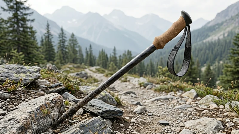
Carbon Fiber Trekking Pole
Lightweight carbon fiber trekking pole manufactured from high-grade carbon fiber tube. Weighs only 160g per pole while providing superior shock absorption and durability for hiking, trail running, and backpacking.