
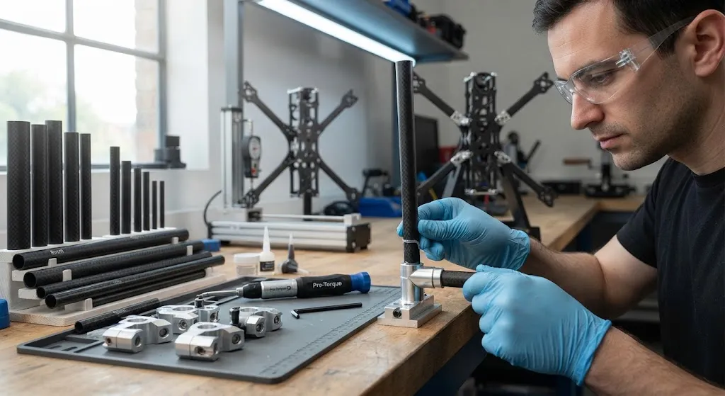
Carbon fiber tube connectors are the components that turn individual composite tubes into a working structure: machined aluminium, injection-moulded nylon, or bonded steel fittings that join two or more carbon fiber tubes at fixed angles. Because carbon fiber tubes are sold as straight, cut-to-lengt
Introduction
Carbon fiber tube connectors are the components that turn individual composite tubes into a working structure: machined aluminium, injection-moulded nylon, or bonded steel fittings that join two or more carbon fiber tubes at fixed angles. Because carbon fiber tubes are sold as straight, cut-to-length sections, every frame — a drone arm, a robot gantry, a lightweight exhibition stand — depends on connectors to carry load between tubes, transfer bending and torsion, and hold alignment over thousands of operating cycles. Choosing the right carbon fiber tube connector is often what separates a durable assembly from one that loosens, creaks, or fails at the joint.
This guide covers the connector types available, how joint strength and stiffness are actually determined, the design rules that prevent premature failure, and the specifications buyers should define when sourcing connectors for a composite frame.
Types of Carbon Fiber Tube Connectors
Connectors for carbon fiber tubes fall into four broad families, each with different load capacity, cost, and assembly characteristics:
- Bonded sleeve and socket joints: A machined aluminium or stainless sleeve is glued over the tube end with structural adhesive. The bond distributes load over a large area, giving the highest joint efficiency, but assembly is permanent.
- Mechanical compression joints: A split collar or clamp is tightened around the tube with screws, gripping the surface without adhesive. These are demountable and adjustable, but the point loads at the clamp edge can crush thin-walled tubes.
- Threaded insert joints: A metal insert with internal threads is bonded into the tube end, allowing a bolt-on connection to brackets or other tubes. This combines a strong bond with the convenience of threaded assembly.
- Over-moulded and printed connectors: Injection-moulded nylon or 3D-printed polymer fittings, often with integrated ribs, are the lowest-cost option for light-duty frames such as tents and drone guards.
The table below summarises the typical performance of each type on a 30 mm outside diameter carbon fiber tube:
| Connector Type | Typical Tensile Capacity | Demountable | Relative Cost | Best For |
|---|---|---|---|---|
| Bonded sleeve (aluminium) | 60-85% of tube strength | No | Medium | Structural frames, permanent joints |
| Mechanical compression clamp | 30-50% of tube strength | Yes | Low | Adjustable fixtures, prototypes |
| Threaded insert (bonded) | 50-70% of tube strength | Partially | Medium-high | Bolted brackets, repeated assembly |
| Over-moulded nylon | 20-40% of tube strength | No | Low | Light frames, tents, guards |
The efficiency figures assume a correctly prepared bond surface. A bonded joint with proper surface abrasion and a structural adhesive such as a two-part epoxy routinely reaches 60-85 percent of the tube's ultimate load, whereas the same joint with a contaminated surface can fall below 20 percent.
How Joint Strength Is Determined
Three variables control the strength of a carbon fiber tube connector joint: bond area, adhesive choice, and the mode of loading. Bond area is proportional to the overlap length times the tube circumference, so a longer sleeve carries more load before the adhesive creeps or peels. As a practical rule, an overlap length of 4-6 times the tube diameter is sufficient for most structural joints; longer overlaps add little strength because the adhesive shear stress is already distributed over a large area.
The table below gives representative design values for a bonded joint on a 25 mm diameter tube with a 100 mm overlap:
| Parameter | Typical Value | Design Note |
|---|---|---|
| Adhesive shear strength | 20-35 MPa | Two-part epoxy, structural grade |
| Recommended overlap | 4-6 x tube diameter | Longer overlap adds little strength |
| Surface preparation | Abrasion + solvent wipe | Removes mould release and dust |
| Gap between tube and sleeve | 0.05-0.20 mm | Keeps adhesive layer thin and uniform |
| Operating temperature | -40 to +120 °C | Epoxy creep above 100 °C |
| Cure time at room temperature | 24-48 hours | Full strength before loading |
Loading mode matters as much as bond area. Axial tension is the friendliest load for a bonded joint because the adhesive works in shear across the whole overlap. Bending puts peak stress at the joint edge, where a sharp sleeve end can act as a stress raiser on the tube; chamfering or rounding the sleeve end and adding a fillet of adhesive removes this local peak. Torsion is the hardest case, which is why torque-carrying connections should use a bonded sleeve plus a transverse pin or a keyed section rather than a plain round glue joint.
Design Rules for Connector Joints
Following a small set of design rules prevents the majority of connector failures seen in field service:
- Never clamp thin-walled tubes directly: A compression clamp on a tube with a wall below 1.5 mm concentrates stress and causes ovalisation and cracking. Use a bonded insert under the clamp or a wider clamp with a rubber liner.
- Chamfer every sleeve end: A sharp metal edge at the end of a bonded sleeve acts as a bending stress raiser and can cut into the composite during flexing.
- Control the adhesive gap: A tight 0.05-0.20 mm gap produces the strongest bond. Loose-fitting connectors rely on a thick adhesive layer that fails in peel.
- Prevent galvanic contact in wet environments: Bare aluminium against carbon fiber in salt or humid service corrodes rapidly. Anodise the aluminium or interpose a glass-fibre insulating layer.
- Design for disassembly where maintenance is expected: If a frame must be packed flat or serviced, choose compression or threaded joints even if the ultimate strength is lower.
For carbon fiber tube connectors used outdoors, ultraviolet exposure also degrades the resin surface over years of sunlight, so the joint area should be protected with paint or an opaque sleeve when the frame is permanently installed.
Applications of Carbon Fiber Tube Connectors
Carbon fiber tube connector systems appear wherever a light, stiff, demountable frame is required:
- Drones and UAVs: Booms and landing gear joined with bonded or clamped connectors that keep weight low and survive crash and landing loads.
- Robotics and automation: Gantry frames and end-effector structures where low inertia improves cycle time and positional accuracy.
- Tents and event structures: Over-moulded and clamped connectors that allow fast, tool-free assembly of light, packable frames.
- Aerospace ground support: Test fixtures, tooling frames, and maintenance stands that must be light enough to move and stiff enough to hold tolerances.
- Marine and outdoor equipment: Mast sections, camera booms, and paddle shafts joined with corrosion-resistant fittings.
- Medical equipment: X-ray-transparent frames and patient positioning structures where metal would cause imaging artefacts.
In each application the economic case follows the same logic: the connector adds a fraction of the system cost, but the joint decides whether the whole frame performs. Spending on the correct connector type and a controlled bonding process returns more reliability than upgrading the tube grade.
Sourcing and Specification Checklist
When buying carbon fiber tube connectors, define the following in writing:
| Specification Item | What to Define | Why It Matters |
|---|---|---|
| Tube outside diameter and wall | Exact OD and wall thickness | Connector bore and clamp range depend on it |
| Connector material | Aluminium 6061-T6, stainless, nylon, or PA-CF | Sets strength, corrosion behaviour, and weight |
| Joint style | Bonded, clamped, threaded, or over-moulded | Determines load capacity and disassembly |
| Adhesive specification | Two-part epoxy, structural grade | Bond performance is only as good as the adhesive |
| Finish | Anodised, powder-coated, or bare | Protects against corrosion and UV |
| Validation data | Pull-test or torque-test certificates | Confirms the joint meets the design load |
Finally, request a sample joint for destructive testing before committing to volume. A single pull test on a bonded sleeve connector tells you more about surface preparation and adhesive quality than any datasheet, and it gives your quality team a baseline against which production batches can be checked.
Frequently Asked Questions
How do I connect two carbon fiber tubes at a 90-degree angle?
The most reliable method is a bonded corner bracket: a machined aluminium or 3D-printed fitting with two sockets at 90 degrees, into which the tube ends are glued with structural epoxy. Prepare both surfaces by light abrasion and a solvent wipe, apply the adhesive, insert the tubes, and hold them square while the adhesive cures. For a demountable version, use a clamp-style corner connector with screws, but accept lower load capacity and add a bonded metal insert inside the tube where the clamp grips. In both cases, keep the overlap at least four times the tube diameter and chamfer the fitting edges to avoid stress raisers.
Can I use metal tube connectors with carbon fiber tubes?
Yes, metal connectors are the most common choice, but two precautions apply. First, in wet or salt service, carbon fiber is cathodic relative to aluminium and will drive galvanic corrosion of the fitting; anodise the aluminium or isolate the surfaces with a thin glass-fibre or polymer layer. Second, any metal connector must be designed so that its edges do not cut into the composite under load — chamfered edges, generous radii, and a bonded insert inside the tube all reduce local stress. For dry indoor frames, bare aluminium or stainless connectors with a bonded joint give excellent long-term performance.
How much weight can a bonded carbon fiber tube joint carry?
A well-made bonded joint typically transfers 60-85 percent of the tube's ultimate tensile load. On a 30 mm outside diameter tube with a 1.5 mm wall, that is roughly 15-25 kN in axial tension with T700 fibre and a 6-diameter overlap. Bending capacity depends on the leverage arm and the joint edge condition, and torsion is lower unless the joint is pinned or keyed. The exact number must come from a pull test on your specific tube, connector, adhesive, and surface preparation, because the bond quality dominates the result — the same geometry with poor surface preparation can drop below 20 percent of tube strength.
Conclusion
Carbon fiber tube connectors determine whether a composite frame is a reliable engineering structure or a collection of fragile tubes. Bonded sleeve and threaded insert joints deliver the highest load capacity when surface preparation and overlap length are controlled, while compression and over-moulded connectors trade strength for demountability and cost. The engineering is well understood: keep the adhesive gap thin, chamfer the metal edges, protect against galvanic corrosion in wet service, and validate every joint style with a destructive test before volume production.
If you are building a carbon fiber frame or replacing a metal structure with a lighter composite one, browse our carbon fiber tube and connector range with tubes in T300, T700, and high-modulus grades plus matching aluminium fittings, or contact our engineering team for joint design guidance and a quote for your project.
Part of topic
Related Articles
Interested in Our Products?
Contact our team for competitive pricing and technical specifications.
Get a QuoteRelated Products

Carbon Fiber Plate — 3K Twill T700 3.0mm
Medium-thickness 3.0mm carbon fiber plate offering significantly higher load capacity while maintaining attractive 3K twill finish. Suitable for structural brackets, reinforcement plates, and load-bearing panels.

Carbon Fiber Plate — 3K Twill T700 1.5mm
Thin 1.5mm carbon fiber plate with 3K twill weave surface. Lightweight and stiff, commonly used for covers, panels, drone bodies, and applications requiring a premium aesthetic appearance.

Square Carbon Fiber Tube — 3K Twill T700
Square cross-section carbon fiber tube manufactured with 3K twill weave for torsional strength. Preferred for structural frames, trusses, and support columns where rectangular geometry offers design flexibility.
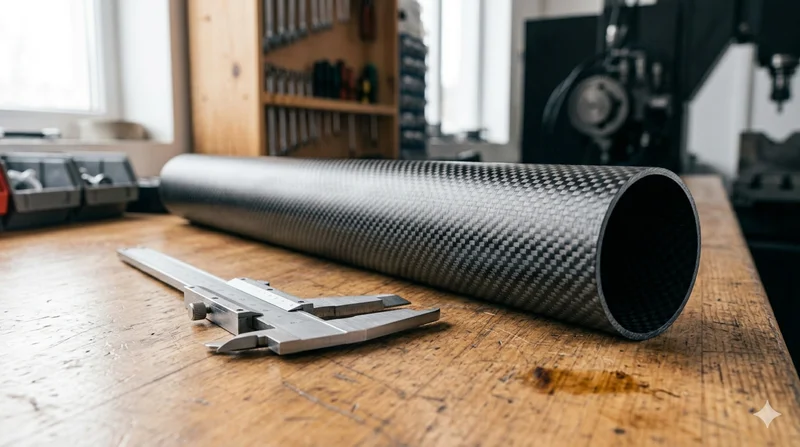
Round Carbon Fiber Tube — 3K Plain Weave T700
Standard round carbon fiber tube manufactured from Toray T700 grade fiber with 3K plain weave. Offers balanced strength and stiffness for general industrial applications including robotics, automation, sports equipment, and aerospace structures.

Round Carbon Fiber Tube — UD Unidirectional T700
Unidirectional (UD) round tube with all fibers aligned axially for maximum longitudinal stiffness. Ideal for applications requiring high bending rigidity with minimal weight, such as shafts, struts, and structural reinforcements.