
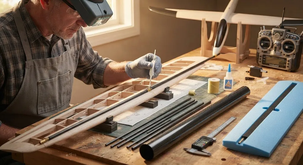
Carbon fiber rods for RC planes solve a specific problem: how to make a lightweight airframe stiff enough to hold its shape under aerodynamic and landing loads. A solid pultruded rod packs the highest bending stiffness into the smallest diameter of any common reinforcement, which is why it appears e
Introduction
Carbon fiber rods for RC planes solve a specific problem: how to make a lightweight airframe stiff enough to hold its shape under aerodynamic and landing loads. A solid pultruded rod packs the highest bending stiffness into the smallest diameter of any common reinforcement, which is why it appears everywhere in model aircraft — as wing spars, wing joiners, tail booms, pushrods, landing gear legs, and leading-edge reinforcement. Compared with the spruce, aluminium, or steel rod it replaces, a carbon rod of the same diameter is lighter and far stiffer, and a rod of the same stiffness is dramatically lighter, which is exactly the trade a model builder wants.
This guide explains the difference between rods, tubes, and strips, how diameter controls stiffness through a very steep relationship, how to size a spar or pushrod for a given model, and the specifications to define when buying carbon fiber rods for RC planes.
Rod, Tube, or Strip: Choosing the Right Form
Carbon fiber is supplied in three forms for airframe work, and each has a different best use:
- Solid pultruded rod: The stiffest and strongest form per unit diameter, because the material is concentrated where bending stress is highest. It is used for pushrods, wing joiners, tail booms, and spars in smaller models where a thin section is essential.
- Roll-wrapped tube: A hollow tube trades a little stiffness for much lower weight at large diameters, and it resists buckling better in compression. It is the better choice for long spars and tail booms on gliders and large-scale models.
- Flat strip (rectangular pultrusion): A thin rectangular section offers high stiffness in the flat plane and low aerodynamic drag, so it is used for wing spars laid into a foam core and for control-surface stiffeners.
The practical rule is to use solid rod where the diameter must stay small, a tube where weight matters most and the section can be larger, and strip where the stiffening must be hidden inside a thin wing.
How Diameter Controls the Stiffness of Carbon Fiber Rods
For a round rod, bending stiffness scales with the fourth power of diameter. That single relationship explains almost every sizing decision in model building: moving from a 2 mm rod to a 3 mm rod does not make the part 1.5 times stiffer, it makes it roughly five times stiffer, doubling the diameter makes it sixteen times stiffer. The table below shows this directly for standard pultruded rod sizes, assuming a density of about 1.5 g/cm³:
| Rod Diameter | Weight (g/m) | Relative Bending Stiffness | Typical RC Plane Use |
|---|---|---|---|
| 1.0 mm | 1.2 | 1.0 | Short pushrods, light tail braces |
| 1.5 mm | 2.7 | 5.1 | Pushrods, small wing spars |
| 2.0 mm | 4.7 | 16.0 | Spars for 1-1.5 m models, joiners |
| 3.0 mm | 10.6 | 81.0 | Main spars for 1.5-2.5 m models |
| 4.0 mm | 18.8 | 256.0 | Spars for 2.5-3 m gliders, landing gear |
| 5.0 mm | 29.5 | 625.0 | Large glider spars and joiners |
| 6.0 mm | 42.4 | 1296.0 | Heavy-lift and large-scale models |
The stiffness column is indexed to the 1 mm rod, so the fourth-power effect is visible at a glance: a 4 mm rod is about 256 times stiffer than a 1 mm rod, for a weight increase of only sixteen times. That is why upsizing a rod, rather than adding a second rod, is usually the efficient way to stiffen a wing.
Sizing a Wing Spar for Your Model
Wing spar sizing follows from the bending moment the wing must carry, which grows with wingspan, flying weight, and the g-load of the tightest manoeuvre. A quick method for a first estimate:
- Estimate the load: Multiply flying weight by the design g-load, typically 4 to 6 g for a sport model and up to 10 g for a fast or aerobatic one.
- Find the bending moment: For a uniformly loaded half-wing, the moment at the root is roughly the half-wing load multiplied by half the semi-span. This is the value the spar must resist.
- Choose a section: Because a rod's stiffness grows as the fourth power of diameter, a small increase in diameter carries a large increase in moment. Where a single rod becomes too large, move to a roll-wrapped tube, which puts the material farther from the neutral axis and resists compression buckling.
- Add a joiner where wings split: The joiner is the most highly loaded part of a two-piece wing. Use a solid rod or thick-walled tube sized for the full root moment, and allow a snug fit with no play, because clearance at the joiner causes flutter and fatigue.
- Protect against compression failure: On the upper spar cap in positive g, the rod is in compression. A solid rod resists this well, but a thin tube can buckle, so keep unsupported tube lengths short with ribs or a shear web.
Pushrods and Control Linkages
A pushrod fails mainly by buckling in compression, not by breaking, and the buckling load scales with the fourth power of diameter divided by the square of length. Two consequences follow for carbon fiber rods for RC planes:
- Length penalises small rods heavily: A 2 mm rod works well up to about 300 mm, but at 600 mm its safe compression load drops sharply, so long runs should step up to 3 mm or 4 mm, or use a tube.
- Support long runs: Adding one or two guide supports along a long pushrod cuts the effective length and raises the buckling load by a factor of four or more, letting a thinner, lighter rod do the job.
- Keep the ends aligned: A pushrod must run straight from servo horn to control horn. Any side load from a misaligned clevis adds bending that a slender rod handles poorly.
- Bond the ends properly: Threaded ends, clevises, and horns are usually glued with cyanoacrylate or epoxy after roughening the rod. A wrapped thread or a short metal sleeve over the joint prevents the rod from splitting under load.
Working with Carbon Fiber Rods for RC Planes
Carbon rods are easy to work but reward a few good habits:
- Cut with the right tool: Use a fine-tooth saw, an abrasive cutoff wheel, or a diamond cut-off; avoid coarse cutters that splinter the fibres. Wrap the cut line with tape to reduce fraying, and always wear a mask, because carbon dust is a respiratory irritant and conductive.
- Roughen before gluing: Bond strength comes from surface preparation. Abrade the rod, clean it, and use cyanoacrylate for quick joints or a toughened epoxy for highly loaded ones.
- Do not rely on friction: A rod pushed into a tube or foam without adhesive will creep and loosen. Always bond or mechanically capture the end.
- Isolate metal: Where an aluminium or steel fitting contacts the carbon in a damp environment, add a thin insulating layer to avoid galvanic corrosion.
Buying Carbon Fiber Rods for RC Planes
When ordering carbon fiber rods for RC planes, define the following in writing:
| Specification Item | What to Define | Why It Matters |
|---|---|---|
| Diameter and tolerance | Nominal mm and plus/minus tolerance | A loose joiner causes flutter; a tight one will not fit |
| Form | Solid rod, roll-wrapped tube, or flat strip | Sets stiffness, weight, and buckling behaviour |
| Fibre and modulus | Standard modulus or high modulus | Higher modulus raises stiffness and cost |
| Length and straightness | Cut length and maximum bow | Straightness is critical for pushrods and joiners |
| Surface finish | Smooth, sanded, or peel-ply | Affects bonding and fit |
| Test data | Flexural modulus or bending test | Confirms the rod meets the load case |
Whether you search for carbon fiber rods for RC planes near me, buy from a local hobby shop, or order from a carbon fiber rods for RC planes USA supplier, verify diameter tolerance and straightness before building, because those two properties, more than fibre grade, decide whether a spar or joiner performs as designed.
Frequently Asked Questions
What diameter carbon fiber rod should I use for a wing spar?
It depends on span and weight, but a practical starting range for solid pultruded rod is 2 mm for models up to about 1.5 m, 3 mm for 1.5-2.5 m, and 4-5 mm for gliders up to 3 m, with a thicker joiner at the wing root. Because stiffness rises as the fourth power of diameter, a small step up in size carries a large gain in stiffness, so err on the larger side and then trim weight elsewhere. For very large or thin wings, a roll-wrapped tube resists compression buckling better than a solid rod of the same weight, so switch to a tube once the unsupported span gets long.
Are carbon fiber rods stronger than aluminium for RC planes?
For stiffness per unit weight, carbon fiber is far ahead. A pultruded carbon rod has a specific stiffness several times that of aluminium, so it does the same stiffening job at a fraction of the weight, which is why it dominates spars and joiners. Carbon is also stronger in tension along the fibre. Its weaknesses are impact and point loading, where it can crack or split rather than bend, and it does not redistribute load the way a ductile metal does. For a plane that must absorb hard landings, combine a carbon rod for stiffness with a metal or plywood element to carry impact energy.
How do I join two carbon fiber rods or fit a joiner?
Cut both ends square, roughen the surfaces, clean them, and bond with a toughened epoxy for structural joints or cyanoacrylate for light ones. A common wing joiner arrangement is a slightly smaller solid rod sliding into a larger tube, bonded at one end so the wing can still separate. Keep the fit snug with no play, because clearance lets the surfaces hammer each other and causes fatigue and flutter. Where the joint carries high load, add a short overwrap of thread or a metal sleeve bonded over the junction to prevent splitting, and avoid any metal-to-carbon contact in damp conditions without an insulating layer.
Conclusion
Carbon fiber rods for RC planes are the model builder's most efficient stiffness tool, because a rod's bending stiffness rises with the fourth power of diameter while weight rises only with the square. That makes upsizing a rod, rather than doubling it, the cheapest route to a rigid wing, and it explains why rod diameter is the number to get right first. Match the form to the job, size the spar and joiner for the real root moment, keep pushrods short and supported, and bond every joint properly.
If you are building or repairing a model aircraft, browse our carbon fiber rod and tube range with solid pultruded rods, roll-wrapped tubes, and flat strip in standard and high-modulus grades, or contact our engineering team for sizing guidance and a quote for your project.
Related Articles
Interested in Our Products?
Contact our team for competitive pricing and technical specifications.
Get a QuoteRelated Products

Carbon Fiber Plate — 3K Twill T700 3.0mm
Medium-thickness 3.0mm carbon fiber plate offering significantly higher load capacity while maintaining attractive 3K twill finish. Suitable for structural brackets, reinforcement plates, and load-bearing panels.

Carbon Fiber Plate — 3K Twill T700 1.5mm
Thin 1.5mm carbon fiber plate with 3K twill weave surface. Lightweight and stiff, commonly used for covers, panels, drone bodies, and applications requiring a premium aesthetic appearance.

Square Carbon Fiber Tube — 3K Twill T700
Square cross-section carbon fiber tube manufactured with 3K twill weave for torsional strength. Preferred for structural frames, trusses, and support columns where rectangular geometry offers design flexibility.

Round Carbon Fiber Tube — UD Unidirectional T700
Unidirectional (UD) round tube with all fibers aligned axially for maximum longitudinal stiffness. Ideal for applications requiring high bending rigidity with minimal weight, such as shafts, struts, and structural reinforcements.
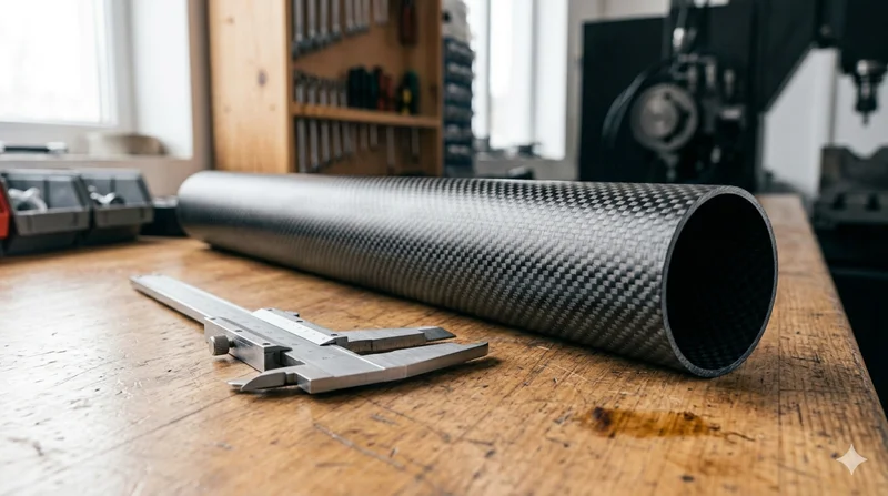
Round Carbon Fiber Tube — 3K Plain Weave T700
Standard round carbon fiber tube manufactured from Toray T700 grade fiber with 3K plain weave. Offers balanced strength and stiffness for general industrial applications including robotics, automation, sports equipment, and aerospace structures.