
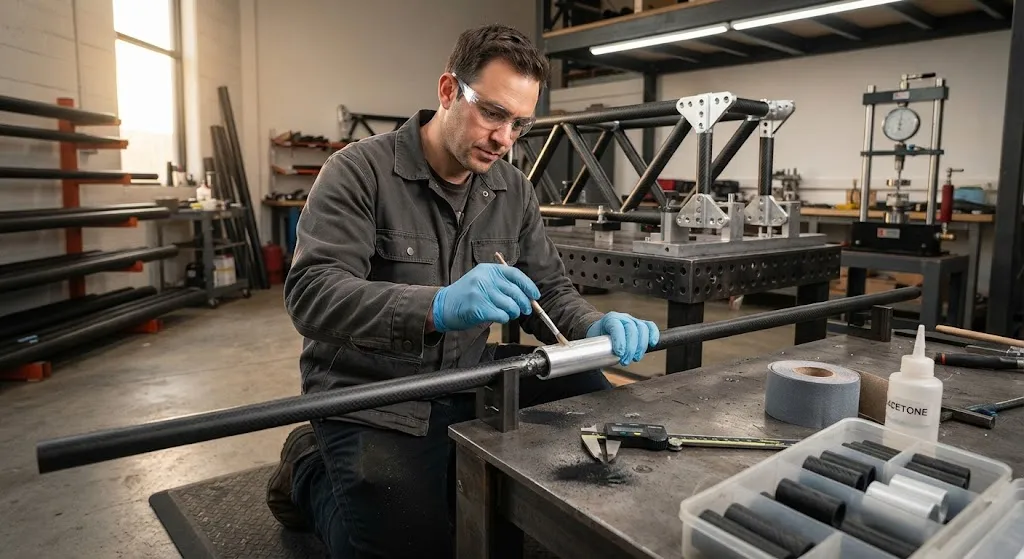
A carbon fiber rod connection is the joint that transfers load from one carbon fiber rod into another rod, a flat plate, or a machined fitting. Solid pultruded carbon rods are strong along their length but they cannot be welded, and a rod end has almost no area to bolt through, so nearly every truss
Introduction
A carbon fiber rod connection is the joint that transfers load from one carbon fiber rod into another rod, a flat plate, or a machined fitting. Solid pultruded carbon rods are strong along their length but they cannot be welded, and a rod end has almost no area to bolt through, so nearly every truss, frame, and mechanism built from rods depends on a designed connection to carry tension, compression, and bending into the rest of the structure. A carbon fiber rod connection decides whether a lightweight frame behaves as one rigid body or as a set of loose sticks that rattle and creep under load. Getting the joint right is usually more demanding than choosing the rod itself, because the rod is often stronger than the connection that anchors it.
This guide explains the connection methods available, how a joint actually develops its strength, the design rules that keep it reliable, and the specifications buyers should define when sourcing carbon fiber rod connection hardware.
Why a Carbon Fiber Rod Connection Controls Performance
A pultruded rod is a near-unidirectional load path: virtually all of its strength runs along the axis, and it has little resistance to local crushing or through-thickness shear. Any connection therefore has two jobs at once, and it must satisfy both without weakening the rod it grips:
- Carry the axial load: The joint must move the full design tension or compression of the rod into the adjoining member without slipping, cracking the resin, or peeling the bond.
- Spread the load gradually: Load must enter the rod over a long bond or contact length, not at a single point, because a concentrated load crushes the rod surface long before the rod itself reaches its tensile limit.
- Tolerate misalignment: Real frames are never perfectly straight, so the connection should absorb small angle errors without locking in bending stress.
- Survive service: The joint must resist moisture, temperature cycling, and repeated assembly without loosening.
Because the connection is almost always the weak link, a frame designed around a good connection can approach the full strength of its rods, while the same rods joined badly may fail at a fraction of their capacity.
Types of Carbon Fiber Rod Connection
Connections fall into four practical families, each trading strength against the ability to assemble, adjust, and service the frame:
- Bonded sleeve: A short carbon or aluminium tube slides over the rod ends and is glued with structural epoxy, giving a stiff, permanent lap joint with the highest efficiency of the simple methods.
- Bonded spigot and socket: The rod end is inserted into a machined socket or a larger tube and bonded, producing an almost invisible, aligned joint that suits truss diagonals and frame corners.
- Mechanical clamp and set screws: A machined collar grips the rod with radial screws or a split clamp, allowing the joint to be assembled and adjusted on site but concentrating stress at each screw.
- Pinned or clevis end: A bonded or threaded metal end fitting with a pin or clevis lets the joint hinge and take out bending, which is the standard approach for folding frames and mechanisms.
The table below compares the typical performance of each method on a 10 mm solid pultruded rod in a truss frame:
| Connection Method | Typical Joint Efficiency | Assembly | Adjustable | Best For |
|---|---|---|---|---|
| Bonded sleeve | 60-85% of rod tensile | Permanent | No | Truss diagonals, rigid corners |
| Bonded spigot and socket | 65-90% | Permanent | No | Aligned frame joints, kite and UAV spars |
| Mechanical clamp and set screws | 30-55% | Demountable | Yes | Adjustable frames, field repairs |
| Pinned or clevis end | 40-65% | Demountable | Limited | Hinged and folding mechanisms |
The efficiency figures are expressed as a percentage of the rod's own tensile capacity. They assume a properly prepared bond or a correctly sized clamp; a bonded joint on a mould-release-contaminated rod surface can fall well below the bottom of its range, which is why surface preparation deserves as much attention as the joint geometry.
How a Carbon Fiber Rod Connection Transfers Load
A bonded carbon fiber rod connection works by shear. The adhesive layer between rod and sleeve transfers axial load tangentially along the bond length, and the stress is highest at the two ends of the overlap and near zero in the middle. That distribution drives the single most important design rule: the bond must be long enough that the peak end stress stays below the adhesive's shear strength. Short overlaps fail by adhesive peel at the mouth, while long overlaps spread the load until the adhesive is no longer the weak link.
Mechanical connections behave differently. A clamp or set screw applies a local radial pressure, and the load is transferred by friction and by bearing on a small contact patch. The rod is strong in tension but weak in cross-wise compression, so an over-tightened screw creates a stress peak that can split the rod along its fibres. Pinned ends introduce a similar concentration where the pin bearing presses on the composite, which is why pinned joints normally use a metal end fitting bonded over a long length rather than a hole drilled straight through the rod.
Design Rules for a Reliable Connection
The rules below cover the variables that decide whether a connection meets its load case:
| Parameter | Recommended Value | Why It Matters |
|---|---|---|
| Bond length | 20-40 x rod diameter | Controls shear load per unit area |
| Adhesive gap | 0.05-0.20 mm | Thin, uniform layer is strongest |
| Sleeve wall thickness | At least equal to rod stiffness | Prevents sleeve splitting before rod |
| Surface preparation | Abrade and solvent-wipe | Can double bond strength |
| Edge distance (pinned joints) | At least 3 x hole diameter | Avoids tear-out of the composite |
| Adhesive service temperature | -40 to +120 °C | Structural epoxy creeps above 100 °C |
Two further details recur in failures. First, avoid abrupt stiffness changes: a rigid metal fitting bonded straight to a flexible rod concentrates load at the bond end, so a tapered or stepped sleeve helps the load enter gradually. Second, account for the difference in thermal expansion between carbon and metal, especially on long outdoor frames, by choosing an adhesive that stays slightly flexible rather than a brittle one.
Common Failure Modes and How to Avoid Them
Most field failures belong to a small set of repeatable categories:
- Adhesive peel at the rod mouth: A sharp edge or a poorly seated bond lets the joint peel open under bending. Chamfer the rod end and the sleeve bore, and add a small adhesive fillet.
- Rod pull-out: Too short a bond length or a loose fit starves the joint of adhesive. Keep the gap thin and the overlap long.
- Sleeve splitting: A sleeve that is thinner or softer than the rod splits before the rod is loaded. Match the sleeve stiffness to the joint load.
- Galvanic corrosion: Bare aluminium in contact with carbon corrodes quickly in wet or salt service. Anodise the fitting or isolate it with a glass-fibre layer.
- Crushing under clamps: Over-tightened set screws dent and split the rod. Use a split collar with a liner, or a bonded end fitting instead.
- Fatigue at the bond end: Repeated bending cracks the adhesive at the joint mouth. Taper the overlap to lower the peak stress.
Sourcing Carbon Fiber Rod Connection Hardware
When buying carbon fiber rod connection parts, define the following in writing:
| Specification Item | What to Define | Why It Matters |
|---|---|---|
| Rod diameter and grade | Exact OD and fibre grade (T300, T700, or high modulus) | Sets sleeve bore and joint capacity |
| Connection type | Bonded, clamped, or pinned | Determines strength and serviceability |
| End fitting material | 6061-T6 aluminium, stainless, or CFRP | Controls weight and corrosion |
| Bond length | 20-40 x rod diameter | Defines pull-out capacity |
| Finish | Anodised, passivated, or bare | Protects against galvanic corrosion |
| Validation data | Tensile and pull-out test certificate | Confirms the joint meets the design load |
Most buyers begin with a search for a carbon fiber rod connection near me or for carbon fiber rod connection suppliers, and many then compare a local machinist with a carbon fiber rod connection USA supplier on price and lead time. Whichever route you take, ask for a tensile and pull-out test certificate on a sample assembly before committing to volume. A single destructive test on your specific rod, sleeve, adhesive, and surface preparation tells you more than any datasheet, and it gives your quality team a baseline for checking production batches. For outdoor and marine frames, confirm the corrosion protection of any metal end fitting at the same time, because a strong joint that corrodes loose in a season is not a reliable joint.
Frequently Asked Questions
How strong is a bonded carbon fiber rod connection?
A correctly made bonded sleeve joint on a 10 mm pultruded rod typically reaches 60 to 85 percent of the rod's own tensile capacity, which for a standard modulus rod is several kilo-newtons of axial load. The exact figure depends on bond length, adhesive shear strength, and surface preparation far more than on the rod grade. A joint with poor surface preparation can lose more than half its capacity, so a pull-out test on the actual assembly is the only reliable number for your design.
Can I connect carbon fiber rods without glue?
Yes, but mechanically. A machined split collar with radial set screws, or a clamp with a fitted liner, lets you assemble and adjust a frame without adhesive. The trade-off is strength: a clamped joint usually carries only 30 to 55 percent of the rod's capacity because the load concentrates at each screw, and over-tightening can crush or split the rod. A pinned or clevis end fitting bonded over a long length is the better choice when you need a demountable joint that still carries high load.
Does a metal fitting cause galvanic corrosion on a carbon rod?
It can. Carbon fiber is cathodic relative to most metals, so a bare aluminium fitting in wet or salt service will drive corrosion of the metal and can eventually loosen the joint. The standard fix is to anodise the aluminium or isolate it from the carbon with a thin glass-fibre or polymer layer. Stainless steel resists better than bare aluminium but is still best isolated. For dry indoor frames the risk is low, but any outdoor, marine, or high-humidity application should treat isolation as mandatory.
Conclusion
A carbon fiber rod connection is a small, inexpensive part that decides whether a rod frame is a rigid structure or a set of loose sticks. Bonded sleeves and spigot-and-socket joints give the highest efficiency for permanent frames, mechanical clamps trade strength for adjustability, and pinned or clevis ends suit hinged and folding mechanisms. The engineering is well understood: choose a long enough bond, keep the adhesive gap thin and uniform, prepare the surface thoroughly, taper stiffness transitions, and protect against galvanic corrosion wherever the frame meets moisture.
If you are building a carbon fiber frame or replacing a metal structure with a lighter composite one, browse our carbon fiber rod and connection range with solid pultruded rods in T300, T700, and high-modulus grades plus matching sleeves, clamps, and end fittings, or contact our engineering team for connection selection and a quote for your project.
Related Articles
Interested in Our Products?
Contact our team for competitive pricing and technical specifications.
Get a QuoteRelated Products

Carbon Fiber Plate — 3K Twill T700 3.0mm
Medium-thickness 3.0mm carbon fiber plate offering significantly higher load capacity while maintaining attractive 3K twill finish. Suitable for structural brackets, reinforcement plates, and load-bearing panels.

Carbon Fiber Plate — 3K Twill T700 1.5mm
Thin 1.5mm carbon fiber plate with 3K twill weave surface. Lightweight and stiff, commonly used for covers, panels, drone bodies, and applications requiring a premium aesthetic appearance.

Square Carbon Fiber Tube — 3K Twill T700
Square cross-section carbon fiber tube manufactured with 3K twill weave for torsional strength. Preferred for structural frames, trusses, and support columns where rectangular geometry offers design flexibility.
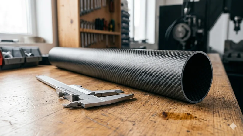
Round Carbon Fiber Tube — 3K Plain Weave T700
Standard round carbon fiber tube manufactured from Toray T700 grade fiber with 3K plain weave. Offers balanced strength and stiffness for general industrial applications including robotics, automation, sports equipment, and aerospace structures.
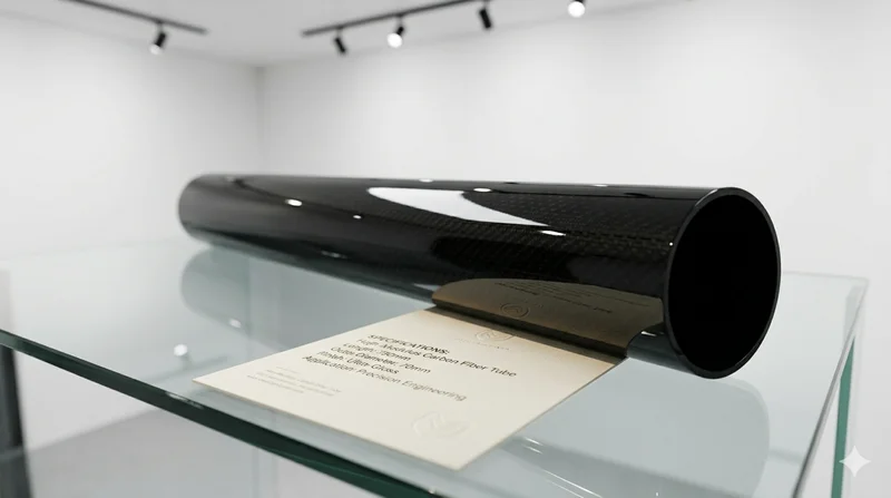
High Modulus Round Carbon Fiber Tube — M40
High modulus round tube manufactured with M40 grade fiber (tensile modulus 400 GPa). Designed for applications where maximum stiffness-to-weight ratio is critical, such as optical systems, precision machinery, and aerospace structures.