
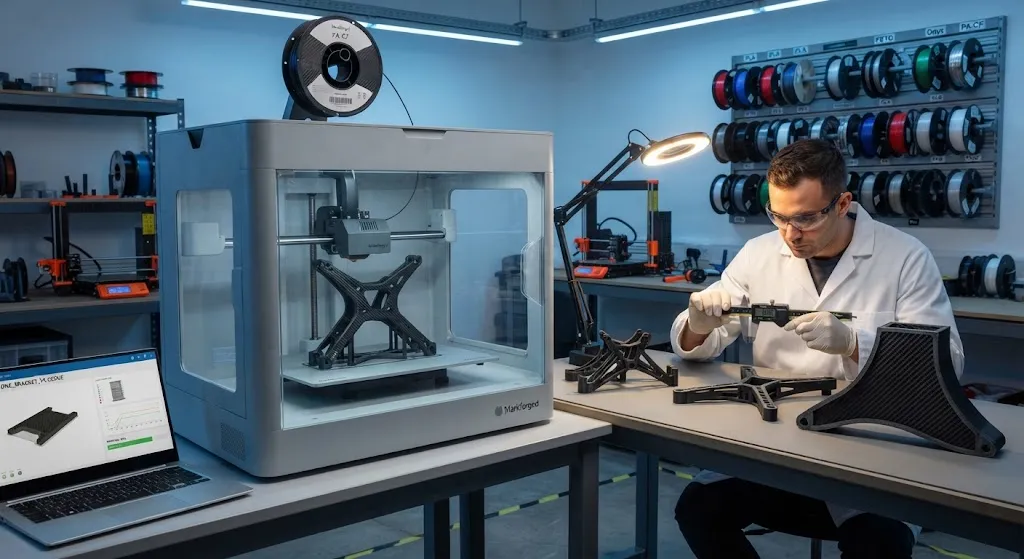
Carbon fiber 3D printed parts are produced by two very different technologies that are often confused. The first, and by far the most common, is FDM printing with a filament reinforced by chopped carbon fiber — a strong, stiff nylon or similar matrix that is significantly tougher than plain filament
Introduction
Carbon fiber 3D printed parts are produced by two very different technologies that are often confused. The first, and by far the most common, is FDM printing with a filament reinforced by chopped carbon fiber — a strong, stiff nylon or similar matrix that is significantly tougher than plain filament but still a conventional thermoplastic part. The second is continuous fiber printing, where a printer lays continuous carbon fiber tows into the part during printing, producing parts with a strength-to-weight ratio approaching that of molded composites. Both have transformed how engineers prototype and produce structural parts, but they serve very different roles in the product development cycle.
This guide explains how each technology works, the strength and stiffness you can actually expect, the design rules that make parts reliable, and how to buy carbon fiber 3D printed parts — from desktop prototypes to production-grade service bureau output.
Carbon Fiber 3D Printed Parts: Chopped vs Continuous Fiber
The table below compares the two technologies on the properties that matter most to engineers:
| Property | Chopped-Fiber Filament (FDM) | Continuous Fiber Printing |
|---|---|---|
| Typical matrix | Nylon, PETG, PLA, or PA-CF | Nylon or PEEK with carbon fiber tows |
| Tensile strength | 50-120 MPa | 400-800 MPa |
| Tensile modulus | 4-10 GPa | 40-120 GPa |
| Fibre volume fraction | 10-20% chopped | 30-50% continuous |
| Part cost | Low — desktop friendly | High — industrial systems or service bureaus |
| Build volume | Large, often 300 mm plus | Smaller, typically 200-400 mm |
| Z-direction properties | Weak layer adhesion | Weak interlayer; in-plane strong |
Chopped-fiber filament is the right choice when you need a stiff, tough, easy-to-print part that is significantly stronger than plain plastic — jigs, fixtures, housings, and prototypes. Continuous fiber printing is the right choice when the part carries real load and needs composite-level stiffness, such as brackets, structural frames, and UAV components, and when the higher cost per part is justified by the performance.
Strength and Stiffness You Can Expect
The mechanical performance of carbon fiber 3D printed parts depends on the technology, material, and orientation of the printed layers. Key points from testing and published data:
- Chopped-fiber parts are roughly 2-4x stiffer than the same part printed in plain nylon or PETG, and about 30-50% stronger, because the fibers stiffen the matrix and improve dimensional stability during printing.
- Continuous fiber parts approach the properties of moulded composites in the plane of the printed fiber: tensile strengths of 400-800 MPa and moduli of 40-120 GPa are achievable with standard carbon fiber tows, though properties drop sharply across the printed layers.
- Z-direction (layer-to-layer) strength remains the weak axis in both technologies. Parts must be oriented so that the highest loads act in the plane of the layers, not across them.
- Annealing and post-processing help: heat treatment can raise the crystallinity of nylon matrices, and continuous-fiber parts can be machined and bonded like conventional composites.
The practical implication is that a continuous-fiber part can replace an aluminium bracket at a fraction of the weight for many structural applications, while a chopped-fiber part is best viewed as a high-performance plastic rather than a composite.
Design Rules for Carbon Fiber 3D Printed Parts
Whether you design parts for your own printer or for a service bureau, these rules determine success:
- Orient loads in the print plane: The X-Y plane carries the fiber; the Z axis is limited by layer adhesion. Design the part so primary loads run along the printed fiber direction.
- Use continuous fiber where loads concentrate: Ribs, flanges, and load paths can be reinforced with continuous fiber while the body of the part prints in chopped-fiber filament — a hybrid strategy that balances strength and cost.
- Specify material and fiber volume explicitly: "Carbon fiber 3D printed" is ambiguous. State the matrix (PA-CF nylon, PETG-CF, etc.), the fiber type (chopped or continuous), and the fiber volume fraction you need.
- Allow for the layer-step surface: Printed parts have visible layer lines and rougher surfaces than molded parts. Specify machining or vapour smoothing where sealing or aesthetics matter.
- Request data sheets and test coupons: A credible supplier provides mechanical data for the specific material and print orientation, not just generic marketing numbers.
These rules apply equally to desktop printers and industrial systems; the difference is in process control and documentation, which is why production parts increasingly come from qualified service bureaus.
Carbon Fiber 3D Printed Parts Across Industry
Carbon fiber 3D printed parts are in production use across several sectors:
- Tooling and fixtures: Lightweight, dimensionally stable jigs and fixtures that are faster to produce and lighter to handle than machined metal equivalents.
- Robotics and automation: End-effectors, grippers, and lightweight arms where mass reduction improves cycle time and reduces motor load.
- Drones and UAVs: Frames, motor mounts, and landing gear produced in small series without expensive mould tooling.
- Automotive: Brackets, ducting, and prototype parts for vehicles and motorsport where low volume makes additive manufacturing the fastest path.
- Aerospace: Non-structural and secondary-structural parts, tooling, and prototypes qualified under controlled processes, with documented material traceability.
- Medical and assistive devices: Custom orthotics, braces, and prosthetics where patient-specific geometry is printed directly from scans.
The common pattern is low-to-medium volume, complex geometry, and a need for strength beyond what plain thermoplastics provide — exactly where additive manufacturing competes best with machining and molding.
Cost and Choosing a Provider
The cost of carbon fiber 3D printed parts varies widely. Chopped-fiber filament costs roughly 2-5 times plain filament per kilogram, and desktop parts are priced accordingly. Continuous-fiber parts are substantially more expensive because of the industrial printers required and the slower build process; service bureau pricing typically reflects material, machine time, and design-for-AM support. As a rule, additive manufacturing is most competitive below a few thousand units, where mould tooling costs cannot be amortised, and for geometries that would require multiple machined parts joined together.
When choosing a provider, verify three things: the specific material system and its published mechanical data, the print orientation and fiber strategy they propose for your loading case, and their quality documentation — batch records, dimensional inspection, and material traceability. A provider that can explain these details is far more valuable than one that quotes only price, particularly for structural or safety-relevant parts.
Frequently Asked Questions
Are carbon fiber 3D printed parts actually as strong as molded carbon fiber?
No — not across all directions. Continuous-fiber 3D printed parts can reach tensile strengths of 400-800 MPa and moduli of 40-120 GPa in the plane of the printed fiber, which approaches molded composite performance. However, the Z-direction (between printed layers) remains weak in both chopped- and continuous-fiber printing, so a printed part is never isotropic like a properly laid-up moulded composite. Chopped-fiber filament parts are roughly 2-4x stiffer than plain nylon or PETG but far below molded composite strength. The correct comparison is application-specific: for in-plane loaded brackets and frames, continuous-fiber printing can genuinely replace moulded or even aluminium parts; for multi-directional loads, moulded composites remain superior.
Can carbon fiber 3D printed parts replace machined aluminium parts?
In many cases, yes, with important caveats. A continuous-fiber printed part can match the stiffness of an aluminium bracket at a fraction of the weight, and the design freedom of printing allows optimised geometries that reduce part count — several machined parts can become one printed part. The caveats are temperature: aluminium parts tolerate service temperatures that exceed most polymer matrices; precision: printed parts have layer-step surfaces and looser tolerances than machined metal unless post-machined; and certification: for safety-critical applications the printed process must be qualified and documented. For prototype and low-to-medium volume production in benign thermal environments, carbon fiber 3D printing is often the faster, lighter, and cheaper route than machining.
What is the best material for carbon fiber 3D printing?
For most engineering parts, nylon reinforced with carbon fiber (PA-CF) is the best all-round choice: it combines high strength and toughness, low moisture absorption relative to unfilled nylon, excellent layer adhesion, and resistance to repeated flexing and impact. PETG-CF is a good lower-cost alternative with easier printing and good stiffness, though less tough than PA-CF. PLA-CF is cheap and dimensionally stable but brittle and unsuitable for load-bearing or warm environments. For demanding applications, PEEK and PEKK with continuous fiber offer the highest temperature resistance and strength, but require high-temperature printers and carry a large cost premium. Choose the matrix for the service environment — temperature, chemicals, impact — and choose chopped versus continuous fiber for the load level.
Conclusion
Carbon fiber 3D printed parts occupy a well-defined place in the manufacturing landscape: they bring composite-level stiffness to additive manufacturing, enabling lightweight structural parts, tooling, and small-series production that would be uneconomical to mould. The technology choice is clear — chopped-fiber filament for high-performance plastic parts, continuous fiber for genuine structural loads — and the design rules, material specifications, and quality documentation that make parts reliable are now well established.
If you are evaluating carbon fiber 3D printing for a project, explore our carbon fiber materials and reinforcement products for conventional composite alternatives, or contact our engineering team to compare 3D printing against molded composite manufacturing for your specific part.
Related Articles
Interested in Our Products?
Contact our team for competitive pricing and technical specifications.
Get a QuoteRelated Products

Carbon Fiber Plate — 3K Twill T700 3.0mm
Medium-thickness 3.0mm carbon fiber plate offering significantly higher load capacity while maintaining attractive 3K twill finish. Suitable for structural brackets, reinforcement plates, and load-bearing panels.

Carbon Fiber Plate — 3K Twill T700 1.5mm
Thin 1.5mm carbon fiber plate with 3K twill weave surface. Lightweight and stiff, commonly used for covers, panels, drone bodies, and applications requiring a premium aesthetic appearance.

Square Carbon Fiber Tube — 3K Twill T700
Square cross-section carbon fiber tube manufactured with 3K twill weave for torsional strength. Preferred for structural frames, trusses, and support columns where rectangular geometry offers design flexibility.
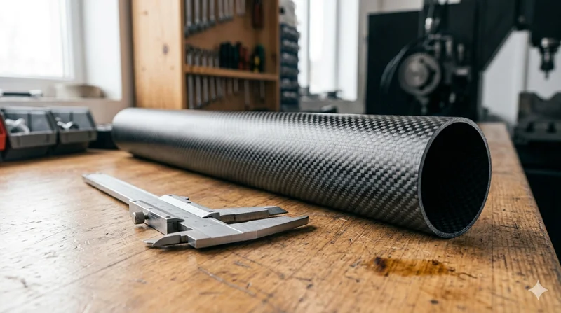
Round Carbon Fiber Tube — 3K Plain Weave T700
Standard round carbon fiber tube manufactured from Toray T700 grade fiber with 3K plain weave. Offers balanced strength and stiffness for general industrial applications including robotics, automation, sports equipment, and aerospace structures.
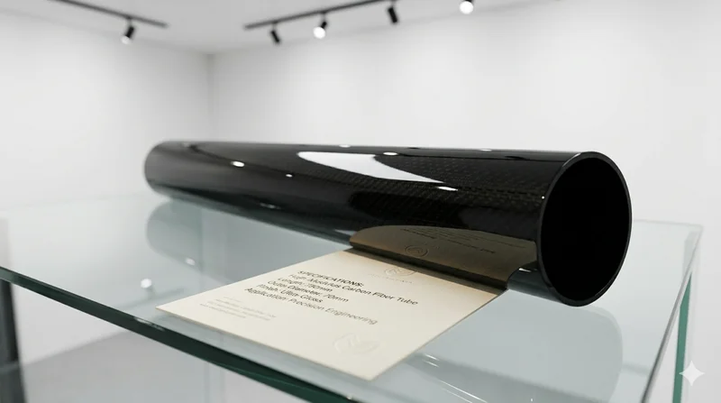
High Modulus Round Carbon Fiber Tube — M40
High modulus round tube manufactured with M40 grade fiber (tensile modulus 400 GPa). Designed for applications where maximum stiffness-to-weight ratio is critical, such as optical systems, precision machinery, and aerospace structures.