
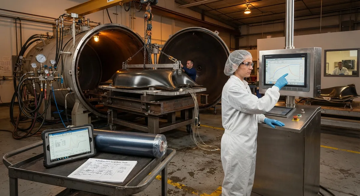
The autoclave remains the gold standard for producing high-quality carbon fiber composite parts, particularly for aerospace and defense applications where void content below 1% and consistent mechanical properties are non-negotiable. However, autoclave processing is energy-intensive and
Introduction
The autoclave remains the gold standard for producing high-quality carbon fiber composite parts, particularly for aerospace and defense applications where void content below 1% and consistent mechanical properties are non-negotiable. However, autoclave processing is energy-intensive and time-consuming: a typical aerospace cure cycle takes 8–14 hours, with autoclave energy consumption of 50–150 kWh per part depending on size and complexity. For manufacturers facing pressure to reduce cost and increase throughput, cure cycle optimization offers one of the highest-impact opportunities.
The challenge is that cure cycle parameters — ramp rate, dwell temperature, dwell time, pressure application timing, and cooling rate — are interdependent and affect both processability and final part properties. Rushing the cycle can cause thermal runaway, trapped volatiles, and residual stress; over-conservative cycles waste energy and capacity. This article explains the principles of cure cycle design, methods for characterizing the process window, and practical strategies for reducing cycle time and energy consumption without compromising part quality.
Fundamentals of Cure Cycle Design
A cure cycle defines the temperature and pressure profile that a composite laminate experiences during processing. The cycle consists of four phases, each with distinct engineering objectives:
- Ramp-up: Heating from room temperature to the first dwell. The ramp rate (typically 1–5°C/min) controls the temperature gradient through the laminate thickness. Faster ramps risk exotherm management issues in thick parts (>20 mm) but reduce total cycle time.
- First dwell (intermediate temperature): A hold at 80–120°C that allows resin to flow and wet out the fibers, air and volatiles to escape, and the laminate to consolidate under pressure. Dwell time depends on laminate thickness and resin viscosity — 15–60 minutes for thin laminates, 30–120 minutes for thick sections.
- Second dwell (cure temperature): A hold at 150–180°C where the epoxy cross-linking reaction occurs. The cure reaction is exothermic — heat generated by the reaction can cause temperature overshoot in thick parts, potentially degrading the matrix. Dwell time of 60–180 minutes ensures complete cure.
- Cool-down: Controlled cooling from cure temperature to room temperature. Cooling rates of 1–3°C/min minimize thermal residual stresses, which cause warpage and dimensional instability if not managed.
Pressure is applied early in the cycle (typically during the first ramp or at the start of the first dwell) at 3–7 bar and maintained through cure to suppress void formation and ensure consolidation.
Characterizing the Cure Process Window
Optimizing a cure cycle requires understanding the resin's rheological and kinetic behavior. Two analytical techniques are essential:
| Technique | Information Obtained | Application |
|---|---|---|
| Differential scanning calorimetry (DSC) | Glass transition temperature (Tg), exotherm onset, degree of cure vs. time | Sets dwell temperatures and times |
| Rheometry | Resin viscosity vs. temperature and time, gel point | Optimizes pressure application timing and first dwell duration |
| Dielectric cure monitoring | Real-time ion viscosity and degree of cure in the actual part | Validates cycle on production parts |
| Dynamic mechanical analysis (DMA) | Final Tg, storage modulus, damping | Confirms cure completion and mechanical property development |
The gel point — where the resin transitions from liquid to solid — is the critical milestone for pressure application. Pressure must be applied before gelation to allow void escape and fiber consolidation, but after sufficient resin flow to ensure complete wet-out. The window between minimum viscosity and gel point defines the optimal pressure application window.
Strategies for Cycle Time Reduction
Reducing cure cycle time requires targeted modifications to each phase while maintaining part quality:
- Faster ramp rates with thick-part thermal management: For laminates thicker than 20 mm, faster ramps (>3°C/min) can cause thermal runaway. Solutions include multi-zone autoclave heating, embedded thermocouple feedback control, and staged heating profiles that slow the ramp as the exotherm peak approaches.
- Optimized first dwell: Many conventional cycles use excessively long first dwells (60–90 minutes) as a safety margin. DSC and rheometry testing can determine the minimum dwell time needed for complete volatile removal and consolidation — often 30–45 minutes for thin-to-medium laminates.
- Reduced second dwell: Cure kinetics modeling (using the Arrhenius equation or Kamal-Sourour model) can predict the time to achieve a target degree of cure (typically 95–98%) at a given temperature. This often reduces the second dwell from 120–180 minutes to 60–90 minutes without measurable property degradation.
- Faster controlled cooling: Increasing cooling rate from 1°C/min to 2–3°C/min can save 20–40 minutes on a typical cycle. The constraint is that cooling rate must not induce thermal stresses exceeding the matrix interlaminar shear strength — finite element analysis can determine the maximum allowable cooling rate for a given geometry.
Collectively, these optimizations can reduce a 10-hour cycle to 6–7 hours — a 30–40% improvement — without changing the resin system or part design.
Energy Reduction Strategies
Autoclave energy consumption is dominated by heating the autoclave vessel and maintaining temperature against heat losses. Three strategies reduce energy per part:
- Vacuum-bag-only (VBO) curing: Eliminating the autoclave entirely by using vacuum pressure (1 bar) instead of elevated pressure (3–7 bar). VBO requires carefully designed resin systems with low volatile content and optimized flow characteristics. Energy savings of 60–80% are achievable, but VBO is limited to less demanding applications or requires process development for aerospace-grade parts.
- Batch optimization: Maximizing autoclave utilization by scheduling parts with compatible cure cycles in the same run. A well-managed batch schedule can reduce per-part energy consumption by 30–50% compared to single-part runs.
- Insulation and heat recovery: Improving autoclave insulation reduces heat losses during the cycle. Heat recovery systems capture waste heat from cool-down and preheat incoming parts or the autoclave vessel, reducing energy consumption by 15–25%.
For manufacturers not ready to transition to out-of-autoclave (OoA) processes, these strategies provide meaningful energy and cost reductions within existing autoclave infrastructure.
Frequently Asked Questions
How much can cure cycle time be reduced without affecting part quality?
Well-characterized cure cycles can typically be reduced by 25–40% from conventional baselines without measurable degradation in mechanical properties. The key is replacing conservative safety margins with data-driven process windows. For example, a conventional aerospace cycle of 10 hours (2-hour ramp, 60-minute first dwell, 120-minute second dwell, 2-hour cool-down) can often be reduced to 6–7 hours through DSC/rheometry-guided optimization. The validated reduction must be confirmed through mechanical testing (void content, fiber volume fraction, interlaminar shear strength, and glass transition temperature) on representative laminates.
What are the risks of reducing cure cycle time?
The primary risks are incomplete cure (reduced Tg and mechanical properties), trapped volatiles (increased void content), and excessive residual stress (warpage and dimensional instability). Thick parts (>20 mm) are most vulnerable to thermal runaway during accelerated ramps, where the exotherm generates heat faster than it can be dissipated. Mitigation strategies include embedded thermocouple monitoring, finite element thermal modeling, and qualification testing on representative laminates before production implementation.
Is vacuum-bag-only curing suitable for aerospace applications?
VBO curing is increasingly used for secondary aerospace structures (fairings, panels, brackets) where void content specifications are less stringent (<2–3% vs. <1% for primary structures). The latest generation of OoA resin systems achieves void contents of 1–2% in VBO processing, approaching autoclave quality. However, primary flight structures (wing skins, fuselage sections) still require autoclave processing for guaranteed void content below 1%. The cost and energy savings of VBO — 60–80% reduction in energy per part — are driving adoption for appropriate applications.
Conclusion
Autoclave cure cycle optimization offers one of the most impactful opportunities for improving composite manufacturing productivity and reducing energy consumption. Data-driven cycle design using DSC, rheometry, and dielectric monitoring can reduce cycle times by 25–40% while maintaining mechanical properties. Combined with batch optimization and insulation improvements, energy consumption per part can be reduced by 30–50%. For manufacturers evaluating cure cycle improvements, the critical first step is characterizing the resin system's cure kinetics and rheological behavior to establish a data-driven process window, rather than relying on conventional conservative cycles.
For buyers evaluating composite manufacturers, the key questions are whether the manufacturer has characterized and validated their cure cycles, the mechanical testing data supporting any cycle reductions, and the energy efficiency metrics of their autoclave operations. Explore our carbon fiber products for autoclave-cured applications, or contact our engineering team to discuss material selection and process optimization for your composite manufacturing program.
Part of topic
Related Articles
- Microwave-Assisted Carbonization for Carbon Fiber: Energy Savings and Quality Improvement
- Carbon Fiber Laser Cutting and Trimming: Automation for High-Volume Production
- Pyrolysis Recycled Carbon Fiber: Mechanical Property Retention and Reuse Applications
- Carbon Fiber Bio-Composites: Natural Fiber Hybrid Reinforcement for Sustainable Applications
- RFID Tracking for Carbon Fiber Supply Chain: Traceability and Quality Assurance
- Infrared Heating for Carbon Fiber Cure: Energy Efficiency and Cycle Time Reduction
Interested in Custom Carbon Fiber Products?
Contact our team for competitive pricing and technical specifications.
Get a QuoteRelated Products
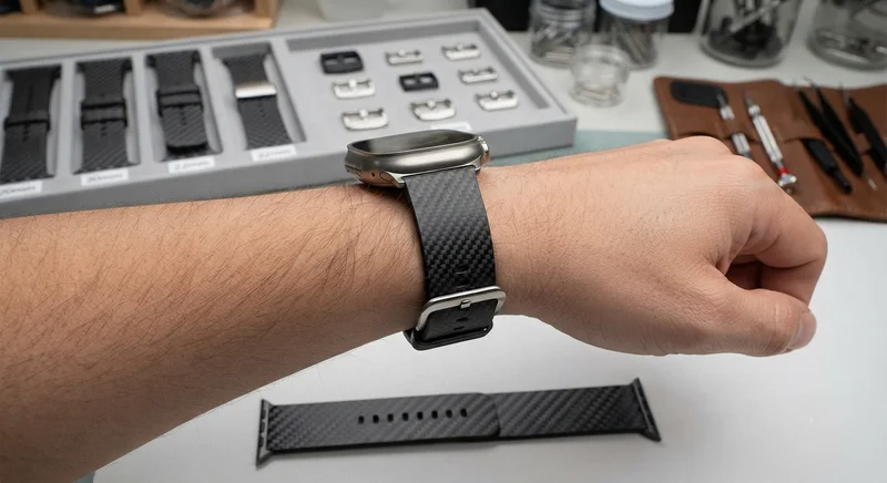
Carbon Fiber Watch Strap — 20mm/22mm Quick-Release
Premium carbon fiber watch strap with quick-release spring bars. Woven from T700 3K twill prepreg with a flexible resin system that conforms to the wrist. Available in 20mm and 22mm lug widths, compatible with Apple Watch, Samsung Galaxy Watch, Garmin, and traditional mechanical watches. Features a stainless steel buckle and carbon fiber keepers. The natural weave pattern makes each strap unique.
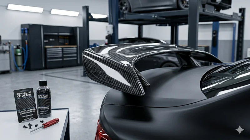
Carbon Fiber Automotive Spoiler
Automotive-grade carbon fiber spoiler manufactured using autoclave-cured pre-preg technology. Each spoiler is vacuum-bagged and oven-cured for optimal fiber-to-resin ratio, strength, and a flawless cosmetic finish.
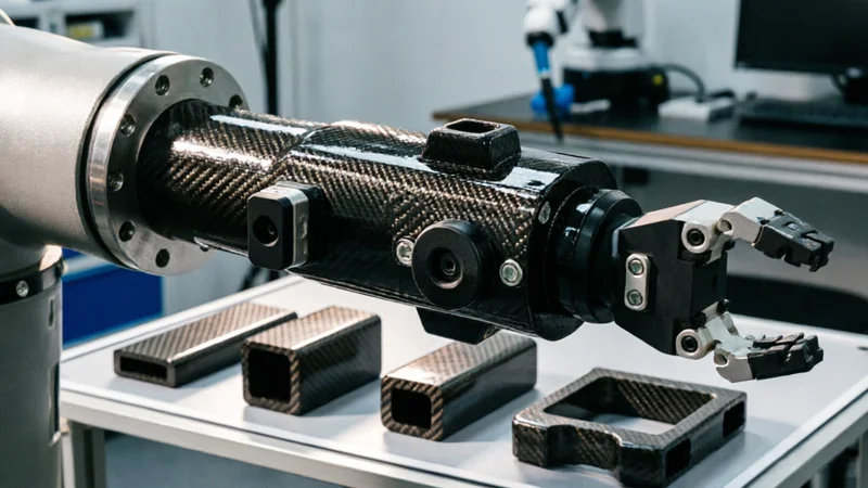
Carbon Fiber Robot End Effector Link — Custom Shape & Sensor Integration
Custom-shaped carbon fiber end effector links for robotic arms. Designed for automation integrators and research labs requiring lightweight, rigid connections between the robot wrist and gripper/tool. Can incorporate sensor mounting bosses, cable routing channels, and quick-change interfaces.
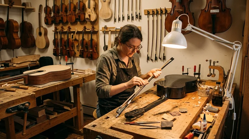
Custom Carbon Fiber Musical Instrument Parts
Carbon fiber components for musical instrument manufacturing offering superior dimensional stability, low weight, and consistent acoustic properties. We produce carbon fiber bows, guitar necks, violin chin rests, drum shells, and wind instrument bodies. Carbon fiber instruments are immune to humidity changes and temperature fluctuations that affect wooden instruments.

Custom Carbon Fiber Medical Device Components
Medical-grade carbon fiber components manufactured for imaging equipment, surgical instruments, and patient support systems. Carbon fiber's radiolucency (X-ray transparency) and high strength-to-weight ratio make it ideal for CT scanner beds, wheelchair frames, surgical robot arms, and MRI-compatible accessories. Biocompatible resin systems available.