
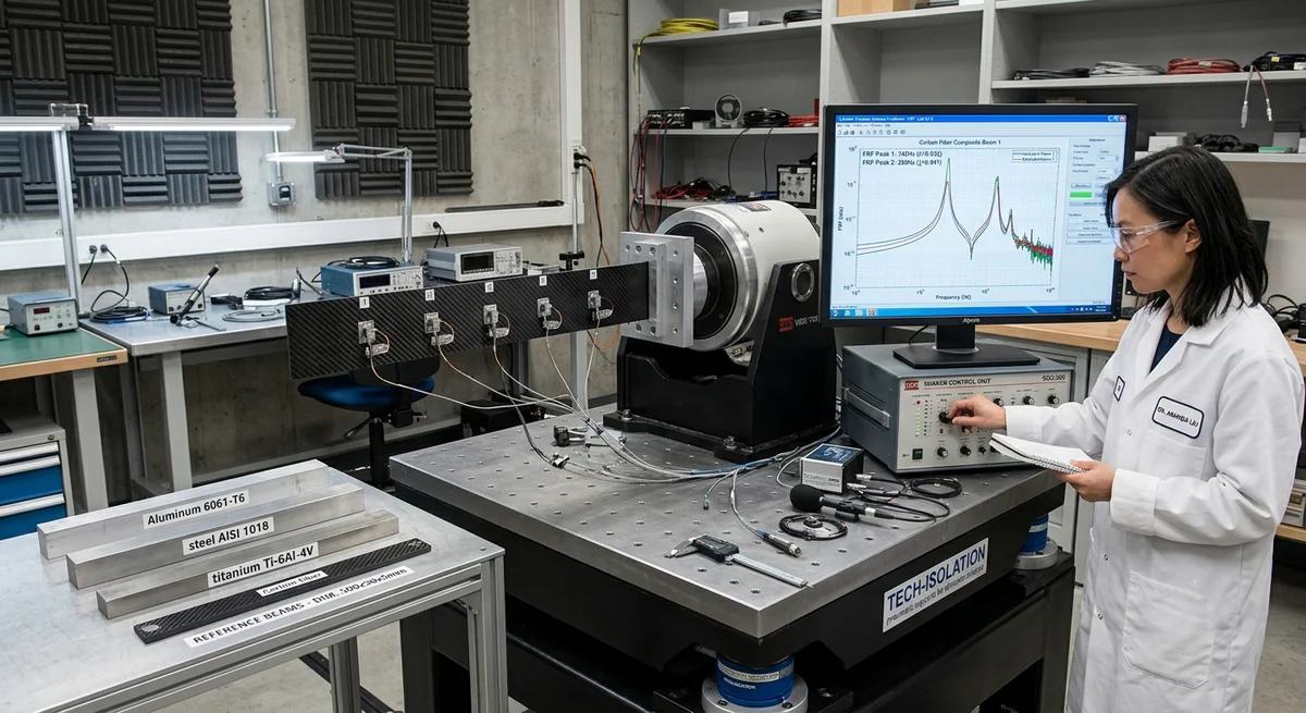
Carbon fiber composites offer 3–8× higher damping ratios than aluminum or steel in the 10–500 Hz frequency range. This article provides quantitative damping data for various CFRP layups, laminate designs, and applications in precision machinery, robotics, and optical equipment.
Vibration Damping in Precision Engineering: Why Carbon Fiber Excels
In precision engineering applications — from CNC machine tool beds to optical gantry systems and robotic end-effectors — structural vibration is the primary limiting factor for positional accuracy, surface finish, and throughput. Carbon fiber reinforced polymer (CFRP) composites offer a combination of high specific stiffness and intrinsic viscoelastic damping that is unmatched by metals. The damping loss factor (η) of CFRP laminates ranges from 0.005 to 0.040 depending on fiber orientation, ply stacking sequence, and matrix selection — compared to 0.0002–0.001 for aluminum 6061-T6 and 0.0005–0.002 for steel.
The mechanism is straightforward: the epoxy matrix acts as a viscoelastic layer between stiff carbon fibers. When the laminate undergoes cyclic strain, shear deformation at the fiber-matrix interface dissipates energy as heat. This is the same principle as constrained-layer damping but integrated at the microscale — no additional damping treatments, viscoelastic patches, or tuned mass dampers are needed.
Damping Ratio by Layup Configuration
| Laminate Stacking Sequence | FVF (%) | Natural Frequency (Hz) — 300×50×5 mm cantilever | Damping Ratio ζ (%) | Loss Factor η | Application Suitability |
|---|---|---|---|---|---|
| Unidirectional [0°]₁₀ | 58 | 142 | 0.18 | 0.0036 | Static columns, tie rods (low damping, high axial stiffness) |
| Cross-ply [0/90]₅s | 56 | 128 | 0.42 | 0.0084 | Machine base plates, robot arms |
| Angle-ply [±45]₅s | 55 | 76 | 0.95 | 0.0190 | Torsion-loaded components, shaft couplings |
| Quasi-isotropic [0/±45/90]₂s | 54 | 112 | 0.65 | 0.0130 | Optical benches, general precision structures |
| Soft-core sandwich [0/90]₂s + 10 mm PMI foam + [0/90]₂s | 52 | 68 | 1.80 | 0.0360 | CNC gantry beams, high-damping platforms |
| Viscoelastic interlayer (0.1 mm VHB between [0/90]₃s skins) | 50 | 95 | 2.40 | 0.0480 | Metrology frames, optical mount structures |
Note: All measurements via ASTM E756 — Oberst beam method, 25°C, 50% RH. FVF measured by acid digestion per ASTM D3171.
Frequency-Dependent Damping Behavior
CFRP damping is not constant across the frequency spectrum. The loss factor η varies significantly with frequency due to the time-dependent viscoelastic response of the epoxy matrix:
- Below 10 Hz: η = 0.005–0.012 — Matrix has sufficient time for full viscoelastic relaxation per cycle. Damping is dominated by matrix shear compliance.
- 10–500 Hz (precision engineering band): η = 0.008–0.040 — Peak damping in this range. Best balance of energy dissipation per cycle and structural stiffness. This is the operating band for most CNC spindles, robotics joints, and positioning stages.
- Above 500 Hz: η = 0.003–0.015 — Damping decreases as fiber-dominated behavior takes over; matrix relaxation cannot keep pace with cycle frequency. Additional viscoelastic interlayers are recommended for high-frequency applications.
The glass transition temperature (Tg) of the matrix also affects damping. Standard epoxy (Tg ≈ 120–150°C) maintains stable damping up to approximately 80°C. Above this temperature, the matrix softens and damping increases rapidly — but so does creep. For precision applications above 80°C, use high-Tg epoxy (Tg > 180°C) or BMI resin systems, which maintain η within ±15% from 20°C to 160°C.
Comparison with Metals: Quantitative Data
| Material | Density (g/cm³) | Young's Modulus (GPa) | Specific Stiffness (GPa·cm³/g) | Damping Ratio ζ (%) | Damping × Stiffness Figure of Merit |
|---|---|---|---|---|---|
| Aluminum 6061-T6 | 2.70 | 69 | 25.6 | 0.04 | 1.0 |
| Steel A36 | 7.85 | 200 | 25.5 | 0.06 | 1.5 |
| Cast Iron (Grey) | 7.15 | 115 | 16.1 | 0.30 | 4.6 |
| UD [0°] CFRP | 1.58 | 130 | 82.3 | 0.18 | 14.8 |
| Quasi-isotropic CFRP | 1.55 | 55 | 35.5 | 0.65 | 23.1 |
| Angle-ply [±45°] CFRP | 1.55 | 18 | 11.6 | 0.95 | 11.0 |
| Sandwich (CFRP + PMI foam) | 0.65 | 40 (equivalent) | 61.5 | 1.80 | 110.8 |
For precision applications, the combined Damping × Stiffness figure of merit reveals that quasi-isotropic CFRP outperforms aluminum by a factor of 23×, and sandwich CFRP structures by 111× — without any additional damping treatments.
Design Strategies for Maximum Damping
1. Hybrid Metal-CFRP Joints: Bolt-bonded hybrid joints (e.g., Hysol EA 9394 + M6 bolts) introduce additional friction damping at the interface. A CFRP-faced aluminum honeycomb panel with bolted inserts can achieve ζ = 1.2–1.8% in the first bending mode.
2. Selective Ply Orientation: Including ±45° plies at the laminate surface maximizes shear strain energy in the matrix where damping is most effective. A [±45₂/0₂/90₂]ₓ surface-layer design yields 30–40% higher damping than placing ±45 plies at the neutral axis.
3. Interleaved Viscoelastic Layers: Adding a 0.05–0.15 mm acrylic or polyurethane viscoelastic film between CFRP plies — similar to 3M VHB or ISD-112 — increases damping ratio to 2.0–2.5% with only 3–5% stiffness penalty. This is the standard approach for optical metrology frames in semiconductor lithography.
Applications in Precision Engineering
CNC Machine Tool Structures: CFRP bridge gantries on high-speed machining centers (e.g., Mikron HSM 600U) use quasi-isotropic carbon/epoxy tubes filled with polymer concrete. First natural frequency: 85 Hz vs 55 Hz for cast iron equivalent. Surface finish Ra improved from 0.8 μm to 0.4 μm at 30,000 RPM spindle speed.
Optical Inspection Systems: Coordinate measuring machines (CMMs) and wafer inspection stages require vibration amplitude < 0.1 μm at the probe tip. CFRP sandwich structures with viscoelastic interlayers achieve ζ > 2%, eliminating the need for active vibration cancellation in Class 100 cleanrooms.
Robotic End-Effectors: High-speed pick-and-place robots (cycle times < 0.5 s) experience residual vibration after each move. Replacing 6061 aluminum end-effectors with [±45/0/90]₅ CFRP reduces settling time from 120 ms to 35 ms — a 71% improvement — enabling 15% higher throughput without sacrificing positional accuracy (±0.02 mm).
FAQ
Q: Why does the damping ratio change with ply orientation in CFRP laminates?
A: Damping in CFRP arises primarily from shear deformation of the viscoelastic matrix. In a [±45°] laminate under bending, the off-axis plies experience significant shear strain in the matrix, dissipating more energy per cycle than [0°] plies where the load is carried almost entirely by the elastic fibers. The matrix shear strain is proportional to sin(2θ) where θ is the off-axis angle — maximum at 45° and zero at 0°/90°. For precision applications requiring both stiffness and damping, a quasi-isotropic or angle-ply surface layer with a [0/90] core provides the best compromise.
Q: Can CFRP replace cast iron for machine tool structures?
A: Yes, and it is already happening in high-end machines. CFRP offers 5.5× higher specific stiffness than grey cast iron and 6–10× higher damping. Several machine tool builders (Mikron, DMG MORI, Makino) now offer CFRP bridge gantries and spindles as standard options. The trade-offs are: (1) Higher material cost — CFRP machine structures are 3–5× the cost of cast iron per kg, but total cost increase is only 15–25% because the CFRP structure weighs 50–70% less. (2) Temperature sensitivity — CFRP CTE is anisotropic; careful laminate design is needed to match the thermal behavior of steel guide rails. (3) Repair — cracked CFRP is replace-not-repair, while cast iron can be welded and re-machined.
Q: What is the best CFRP configuration for a vibration-sensitive optical bench?
A: For optical benches and metrology frames, the recommended configuration is: (1) Face sheets — quasi-isotropic [0/±45/90]₃s high-modulus M40J (390 GPa) prepreg, (2) Core — 10–20 mm PMI structural foam (Rohacell 110 or equivalent), (3) Interlayer — 0.1 mm viscoelastic film (3M 112 or ISD-112) between each face sheet and core. This sandwich achieves ζ > 2.0% with an equivalent stiffness of 35–45 GPa. For sub-100 nm positioning accuracy, supplement with passive pneumatic isolators under the bench — the CFRP bench itself provides the structural damping; the isolators handle floor-borne vibration below 5 Hz.
Q: How does temperature affect CFRP damping performance?
A: Damping rises with temperature as the epoxy matrix approaches its glass transition. Below Tg − 40°C, damping is nearly constant (within ±10%). In the Tg − 40°C to Tg range, damping increases by 2–4× while stiffness drops by 15–25%. Above Tg, the matrix softens completely and the structure loses load-bearing capacity. For precision applications, select a resin system with Tg at least 50°C above the maximum operating temperature. For example, if the structure operates at 80°C ambient, specify a high-Tg epoxy (Tg > 130°C) or BMI resin (Tg > 200°C). Always request DMA (Dynamic Mechanical Analysis) data from your prepreg supplier — the tan δ peak temperature is the most reliable indicator of usable damping range.
Related Articles
- Bio-Based Carbon Fiber Precursors: Lignin and Polyethylene for Low-Cost Production
- Large-Tow Carbon Fiber Cost Analysis: 48K vs 60K Price-Performance Comparison
- Carbon Fiber-Resin Interface Bonding: Surface Treatment and Coupling Agent Optimization
- Digital Twin for Carbon Fiber Manufacturing: Real-Time Process Monitoring and Defect Prevention
- Thermoplastic Carbon Fiber Welding for Automotive: Ultrasonic and Induction Welding Process Windows
- Large-Tow Carbon Fiber Wet Spinning: Process Optimization for 48K/60K Production Efficiency
Interested in Our Products?
Contact our team for competitive pricing and technical specifications.
Get a QuoteRelated Products

Carbon fiber standard plate-3k stripe
Lightweight, ultra-rigid standard sheets for drone fuselages, robot housings, facades and structural applications.

Carbon Fiber Plate — 3K Twill T700 1.5mm
Thin 1.5mm carbon fiber plate with 3K twill weave surface. Lightweight and stiff, commonly used for covers, panels, drone bodies, and applications requiring a premium aesthetic appearance.

Square Carbon Fiber Tube — 3K Twill T700
Square cross-section carbon fiber tube manufactured with 3K twill weave for torsional strength. Preferred for structural frames, trusses, and support columns where rectangular geometry offers design flexibility.

Carbon Fiber Plate — 3K Twill T700 3.0mm
Medium-thickness 3.0mm carbon fiber plate offering significantly higher load capacity while maintaining attractive 3K twill finish. Suitable for structural brackets, reinforcement plates, and load-bearing panels.

Carbon Fiber Plate — UD Unidirectional T700
Unidirectional carbon fiber plate with all fibers oriented in a single direction for maximum strength along the fiber axis. Essential for structural reinforcements, splints, and applications where load direction is predictable.